8421 encoder, 4-wire-2 wire encoder, priority encoder, etc. Do you understand the principles of these encoders
8421 encoder, 4-wire-2 wire encoder, priority encoder, etc. Do you understand the principles of these encoders
8421 encoder, 4-wire-2 wire encoder, priority encoder, etc. Do you understand the principles of these encoders
Definition and function of encoder
In digital systems, it is often necessary to transform a certain information (input) into a certain code (output). Arrange binary codes according to certain rules, such as 8421 codes, Gray codes, etc., so that each group of codes has a specific meaning (representing a certain number or control signal) is called a code. The logic circuit with encoding function is called encoder. The encoder has several inputs, and only one input signal is converted into a binary code at a certain time. If an encoder has N input terminals and n output terminals, the relationship between the output terminal and the input terminal should satisfy the relationship N≤2n. For example, 8-wire-3 wire encoder and 10-wire-4 wire encoder have 8 input, 3-bit binary code output and 10-input, 4-bit binary code output respectively.
▲ 4-wire-2 wire encoder
The working principle of an encoder with 4 inputs and 2 binary outputs is analyzed below.
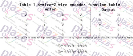
The logic circuit can realize the functions shown in Table 1

That is, when one of the inputs I0~I3 is 1, the output Y1Y0 is the corresponding code. For example, when I1 is 1, Y1Y0 is 01. There is one more issue here for readers' attention. When I0 is 1, I1~I3 are all 0 and I0~I3 are all 0, Y1Y0 are all 00, and these two situations must be distinguished in practice. This problem is left to be solved later. Of course, the encoder can also be designed to be active low.
▲ Keyboard input 8421BCD code encoder
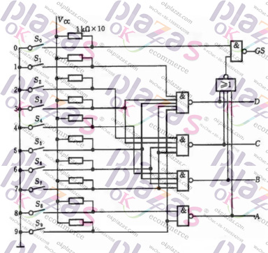
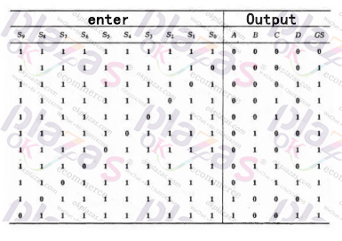
The keyboard input logic circuit of the computer is composed of an encoder. Figure 2 is an 8421 code encoder composed of ten buttons and gate circuits. Its functions are shown in Table 2. Among them, S0~S9 represent ten buttons, that is, input keys corresponding to decimal numbers 0-9, and their corresponding output codes It happens to be 8421BCD codes, and they are also used as logic variables, ABCD is the output code (A is bit), and GS is the control enable flag.
Analyzing the function table and logic circuit, we can know that: ①The encoder is input low-level valid; ②When any key of S0~S9 is pressed, that is, when one of the input signals is at valid level, GS =1, it means there is signal input, and only when S0~S9 are all high level, GS=0, it means no signal input, the output code 0000 at this time is invalid code. This solves the problem of how to distinguish the two cases where the output is all 0.
▲ Priority encoder
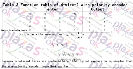
Although the above-mentioned mechanical key coding circuit is relatively simple, when two or more keys are pressed at the same time, its output will be confused. In digital systems, especially in computer systems, several work objects are often controlled. For example, a microcomputer host needs to control printers, disk drives, and input keyboards. When a component needs to perform an operation, it must first send a signal to the host (called a service request), and then send an allow operation signal (called a service response) after the host recognizes it. There will be several components that simultaneously issue a service request Possibly, but only one of the components can be signaled to allow operation at the same time. Therefore, it is necessary to specify the order of permitted operations of these control objects, that is, the priority level, according to the priority. The logic component that recognizes the priority level of this type of request signal and encodes it is called a priority encoder. The function table of 4-wire-2 wire priority encoder is shown in Table 3.
The working principle and types of encoders
Encoder is a device that compiles and converts signals (such as bit streams) or data into signal forms that can be used for communication, transmission and storage. The encoder converts angular displacement or linear displacement into electrical signals. The former is called a code wheel and the latter is called a code ruler. Encoders can be divided into contact type and non-contact type according to the reading mode; encoders can be divided into two types: incremental type and type according to the working principle. The incremental encoder converts the displacement into a periodic electric signal, and then converts this electric signal into a counting pulse, and the number of pulses is used to indicate the magnitude of the displacement. Each position of the type encoder corresponds to a certain digital code, so its indication is only related to the start and end positions of the measurement, and has nothing to do with the middle process of the measurement.
According to the detection principle, encoders can be divided into optical, magnetic, inductive and capacitive. According to its scale method and signal output form, it can be divided into three types: incremental type, type and mixed type.
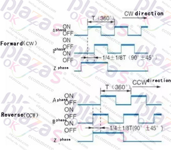
Incremental encoder: Incremental encoder directly uses the principle of photoelectric conversion to output three sets of square wave pulses A, B and Z; the phase difference of the two sets of pulses A and B is 90 degrees, so that the direction of rotation can be easily determined. The Z phase is one pulse per revolution, used for reference point positioning. Its advantages are simple structure, average mechanical life of more than tens of thousands of hours, strong anti-interference ability, high reliability, and suitable for long-distance transmission. The disadvantage is that the position information of the shaft rotation cannot be output.
Type encoder: Type encoder is a sensor that directly outputs numbers. There are several concentric code discs along the radial direction on its circular code disc. Each track is composed of light-transmissive and opaque sectors. Adjacent codes The sector trees of the track are in double relationship. The number of code channels on the code disc is the number of binary digits. On one side of the code disc is the light source, and the other side has a photosensitive element corresponding to each code track. When in different positions, each photosensitive element converts a corresponding level signal according to whether it receives light or not to form a binary number. The characteristic of this kind of encoder is that no counter is needed, and a fixed digital code corresponding to the position can be read out at any position of the shaft. Obviously, the code channel must be N code channels. At present, there are 16-bit encoder products in China.
Hybrid encoder: Hybrid encoder, it outputs two sets of information, one set of information is used to detect the magnetic pole position, with information function; the other set is exactly the same as the output information of the incremental encoder.
Application of photoelectric encoder
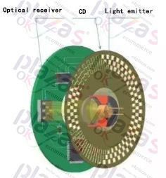
The photoelectric encoder expresses the position information of the motor rotor connected to the photoelectric encoder by reading the pattern or code information on the photoelectric encoder disc. The photoelectric encoder is the most widely used sensor at present.
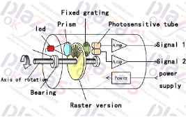
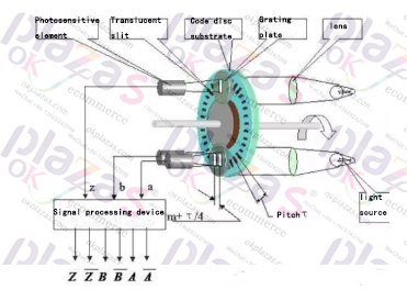
The general photoelectric encoder is mainly composed of a grating disc and a photoelectric detection device. In the servo system, since the photoelectric code disc is coaxial with the motor, when the motor rotates, the grating disc rotates at the same speed as the motor, and a detection device composed of light-emitting diodes and other electronic components detects and outputs several pulse signals. The current motor speed can be reflected by calculating the number of output pulses of the photoelectric encoder per second. In addition, in order to determine the direction of rotation, the code wheel can also provide two-channel optical code output with a phase difference of 90°, and determine the rotation of the motor according to the state change of the dual-channel optical code.
According to the working principle of the photoelectric encoder, the photoelectric encoder can be divided into a photoelectric encoder and an incremental photoelectric encoder. Below, briefly explain the difference between incremental encoder and type encoder.
1, angle measurement
Car driving simulator, the measurement of steering wheel rotation angle uses photoelectric encoder as sensor. The gravity measuring instrument uses a photoelectric encoder to connect its shaft to the compensation knob shaft of the gravity measuring instrument. The torsion angle meter uses the encoder to measure the torsion angle changes, such as torsion experiment machine, fishing rod torsion fishing performance test, etc. The pendulum impact test machine uses an encoder to calculate the swing angle change during impact.
2, length measurement
The meter counter uses the circumference of the roller to measure the length and distance of an object. The cable displacement sensor uses the circumference of the winding wheel to measure the length of the object. Direct coupling measurement, coupled with the main shaft of the power device that drives linear displacement, and measured by the number of output pulses. In the medium detection, the linear displacement information is transmitted on the straight rack, the sprocket of the rotating chain, and the synchronous belt wheel.
3, speed measurement
Linear speed, measure the linear velocity and angular velocity of the production line by connecting with the instrument, and measure the speed of the motor, shaft, etc. through the encoder
4. Position measurement
On the machine tool, the coordinate position of each coordinate point of the machine is memorized. For automatic control such as a drilling machine, it controls the designated action at each position. Such as elevators, hoists, etc.
5, synchronous control
Through angular velocity or linear velocity, the transmission link is synchronously controlled to achieve tension control
Incremental encoder (rotary type)
Rotary encoder is a device used to measure speed. It is divided into two types: single output and dual output. Technical parameters mainly include the number of pulses per revolution (dozens to thousands of them), and power supply voltage. Single output means that the output of the rotary encoder is a set of pulses, while the dual output rotary encoder outputs two sets of pulses with a phase difference of 90 degrees. The two sets of pulses can not only measure the speed, but also determine the direction of rotation.
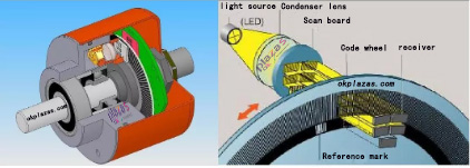
1. Working principle: A photoelectric code disc with an axis in the center, on which there are ring-shaped and dark engraved lines, is read by photoelectric transmitting and receiving devices, and four groups of sine wave signals are combined into A, B, C, D ,Each sine wave has a phase difference of 90 degrees (relative to a cycle of 360 degrees), the C and D signals are reversed and superimposed on the A and B phases to enhance the stable signal; in addition, a Z-phase pulse is output per revolution To represent the zero reference position.
Since the phases A and B are 90 degrees apart, the encoder's forward and reverse rotation can be judged by comparing the phase A or the phase B. The zero reference position of the encoder can be obtained through the zero pulse.
The materials of the encoder code disc are glass, metal, plastic. The glass code disc is deposited on the glass with very thin scribe lines, which has good thermal stability and high precision. The metal code disc is directly engraved with through and impassable lines and is not fragile. However, due to the certain thickness of metal, the accuracy is limited, and its thermal stability is one order of magnitude worse than that of glass. Plastic code discs are economical, and their cost is low, but accuracy, thermal stability, and life are worse.
Resolution—The number of open or dark engraved lines provided by the encoder per 360 degree rotation is called resolution, which is also called resolution division, or directly called the number of lines, generally 5 to 10,000 lines per revolution.
2. Signal output: The signal output has sine wave (current or voltage), square wave (TTL, HTL), open collector (PNP, NPN), push-pull multiple forms, of which TTL is a long-line differential drive (symmetrical A, A -;B,B-;Z,Z-), HTL is also called push-pull, push-pull output, the signal receiving device interface of the encoder should correspond to the encoder.
Signal connection—The pulse signal of the encoder is generally connected to the counter, PLC, and computer. The modules connected between the PLC and the computer are divided into low-speed modules and high-speed modules, and the switching frequency is low or high.
Such as single-phase connection, used for single direction counting and single direction speed measurement.
A.B two-phase connection, used for forward and reverse counting, judgment of forward and reverse and speed measurement.
A, B, Z three-phase connection, used for position measurement with reference position correction.
A, A-, B, B-, Z, Z-connections, due to the connection with symmetrical negative signals, the electromagnetic field contributed by the current to the cable is 0, attenuation, anti-interference, and can be transmitted over a long distance.
For TTL encoders with symmetrical negative signal output, the signal transmission distance can reach 150 meters.
For HTL encoders with symmetrical negative signal output, the signal transmission distance can reach 300 meters.
3. Problems with incremental encoders: incremental encoders have zero cumulative errors and poor anti-interference. The receiving equipment needs to be powered off and remembered when it is shut down, and it should be changed or referenced when it is turned on. These problems, such as the choice of coding The device can be solved.
General application of incremental encoder:
Speed measurement, measurement of rotation direction, measurement of movement angle, distance (relative).
type encoder (rotary type)
There are many optical channel engraved lines on the encoder optical code disc, and each engraved line is in order of 2, 4, 8 and 16 lines. . . . . . Arrangement, in this way, at each position of the encoder, by reading the open and dark of each engraved line, a set of binary codes from the zero power of 2 to the n-1 power of 2 (Gray code ), which is called an n-bit encoder. Such an encoder is determined by the mechanical position of the photoelectric code disc, and it is not affected by power failure or interference.
Each position of the encoder is determined by the mechanical position. Yes, it does not need to be memorized, no need to find a reference point, and no need to count all the time. When you need to know the position, when to read its position. In this way, the anti-interference characteristics of the encoder and the reliability of the data are greatly improved.
From single-turn encoder to multi-turn encoder
Rotate a single-turn encoder to measure each engraved line of the photoelectric code disk during rotation to obtain the code. When the rotation exceeds 360 degrees, the code returns to the original point. This does not comply with the principle of coding. Such code can only be used The measurement within 360 degrees of rotation is called a single-turn encoder.
If you want to measure the rotation range beyond 360 degrees, you need to use a multi-turn encoder.
The encoder manufacturer uses the principle of clock gear mechanism. When the center code wheel rotates, another set of code discs (or multiple sets of gears, multiple sets of code discs) are driven by gears, and the number of turns is added to the single-turn encoding. Encoding, in order to expand the measuring range of the encoder, such an encoder is called a multi-turn encoder, it is also determined by the mechanical position of the code, each position code is not repeated, without the need to remember.
Another advantage of multi-turn encoders is that due to the large measuring range, the actual use tends to be richer. In this way, it is unnecessary to find the change point during installation. It is enough to use a certain intermediate position as the starting point, which greatly simplifies the difficulty of installation and debugging.
-
The principle and application field of Autonics panel products (handling)
 June 12, 2021
 -
New product launch SRH1 series single-phase SSR with integrated heat sink
 June 12, 2021
 -
New product launch SRH1 series single-phase SSR with integrated heat sink
 June 12, 2021
 -
Otto protection grade IP69K new product launched Ø18mm cylindrical (SUS316L housing) photoelectric sensor BRQT series
 June 12, 2021
 -
Autonics adds shading motion mode sensor
 June 12, 2021