About the interface mode of STM32 encoder
About the interface mode of STM32 encoder
Encoder is a relatively common product (can also be understood as a sensor), the most common is to work with the motor, then, how much do you know about the encoder?
1.About the encoder
There are many types of encoders: incremental encoder, absolute encoder, shaft or shaftless encoder, voltage output, push-pull output, open collector output and so on. But no matter what type of encoder, its purpose is similar, to get the angle of rotation, angular velocity, displacement, etc. This article talks about common incremental encoders. Incremental encoders can also be called quadrature encoders. That is to say, you can know whether the encoder is forward or reverse through the phases of A and B, and can also be based on encoder parameters Find out how many angles have been rotated, etc. What do the three lines A, B and Z of the common incremental encoder mean? It’s easy for people who have used encoders to understand, here is a brief introduction to beginners: A and B lines provide pulse signals with a phase difference of 90 degrees, and use them to calculate the angle of rotation; Z line is the zero-crossing line, that is For each revolution, a pulse signal will be output after a certain point, which is mainly used for "zero-crossing correction". The three-wire signal is roughly as follows:
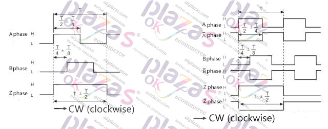
Some encoder lines have a corresponding "not" signal line (as shown on the right side of the figure above), which is actually used for anti-interference. For more descriptions of encoders, please search for relevant knowledge on the Internet to understand, this article will not describe it.
Two, STM32 encoder interface mode
In the STM32 chip, there is such a timer, called "General-purpose timers", there is such a mode in the timer, called the encoder interface mode "Encoder interface mode". Of course, you can refer to the data sheet corresponding to the chip for details.
The encoder interface mode provided by STM32 is mainly aimed at the "quadrature encoder", which can use the timer's "counting" function to get how many pulses the encoder counts; at the same time, it can be obtained according to the phase of the encoder AB Indicates whether the encoder is rotating forward or reverse.
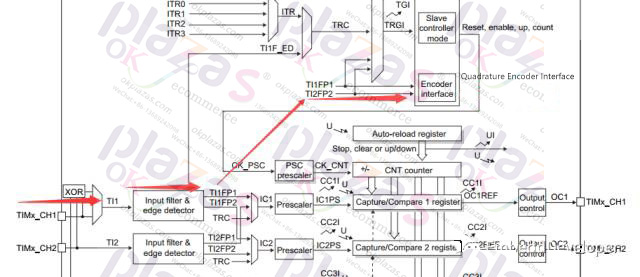
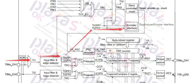
(The picture comes from the STM32 reference manual)
1. Calculate the number of pulses
Similar to the capture function of TIM, it captures the pulse signals of phase A and phase B; but the encoder mode is to capture the edge signals of phase A (TI1) and B (TI2) (as shown in the figure above), which is equivalent to 4 in one cycle The value of the pulse signal.
2. Increase and decrease of the counter (direction)
The counter of STM32 will count according to the direction (+ or -). The phase difference between TI1 and TI2 is 90. The four-stage edges correspond to the different level signals of TI1 and TI2. From this different signal, the hardware itself can determine its direction. . In the encoder mode, there is a direction bit (DIR) in a register (TIMx_CR1), which will change with the change of the rotation direction of the encoder. We can read this bit to determine whether the encoder is rotating forward or backward. turn.
3.TIM time base
The STM32 encoder interface mode actually uses the AB phase TIM time base to provide a clock signal to make it count.
Three, application programming
I believe that after reading some of the above descriptions, everyone should understand the encoder. In fact, in STM32, you can obtain the information on the encoder sensor by configuring the function corresponding to the encoder mode.
Use the standard peripheral library provided by STM32, or use the STM32CubeMX tool to easily configure the TIM into encoder mode.
1. Standard peripheral library configuration encoder
TIM_EncoderInterfaceConfig, it is the configuration function of the encoder interface. Simply configure this function and enable TIM to collect the information on the encoder. (Of course, complex operations are required, and other corresponding configurations are also required)
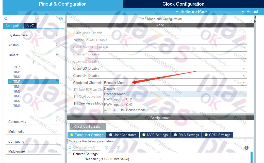
2.STM32CubeMX configuration
STM32CubeMX is a set of rapid development tools, allowing many friends who do not understand the underlying STM32 to quickly write applications on STM32.
In the configuration encoder interface mentioned in this article, there is a "Combined Channel" configuration on some TIMs, which can be understood as a "connection channel", which can also be regarded as a multiplexing mode of TIM. Select "Encoder Mode" inside.
Four, example code
The code provided in this article is a simple Demo project written using the standard peripheral library, which includes a project (the project used to simulate the AB phase waveform of the encoder), as follows:
The project mainly configures the encoder mode of TIM, and reads the direction (DIR) and count (CNT) of the encoder through timing, and prints it out through the serial port.
download link:
GitHub:
https://github.com/EmbeddDeveloper/STM32F4_TIM_Encoder
Tip: The public account does not support external links, please copy the link to the browser to open;
-
The principle and application field of Autonics panel products (handling)
 June 12, 2021
 -
New product launch SRH1 series single-phase SSR with integrated heat sink
 June 12, 2021
 -
New product launch SRH1 series single-phase SSR with integrated heat sink
 June 12, 2021
 -
Otto protection grade IP69K new product launched Ø18mm cylindrical (SUS316L housing) photoelectric sensor BRQT series
 June 12, 2021
 -
Autonics adds shading motion mode sensor
 June 12, 2021