Analysis of brushless DC motor FOC, square wave, sine wave control!
Analysis of brushless DC motor FOC, square wave, sine wave control!
Analysis of brushless DC motor FOC, square wave, sine wave control!
The brushless DC motor is developed on the basis of the brush DC motor. It has the advantages of stepless speed regulation, wide speed regulation range, strong overload capacity, good linearity, long life, small size, light weight, and large output. In order to solve a series of problems in brush motors, they are widely used in various fields such as industrial equipment, instrumentation, household appliances, robots, and medical equipment. Since the brushless motor has no brushes for automatic commutation, an electronic commutator is needed for commutation. The brushless DC motor driver realizes the function of this electronic commutator.
Mainstream brushless DC motor control method
There are currently three main types: FOC (also known as vector frequency conversion, magnetic field vector oriented control), square wave control (also known as trapezoidal wave control, 120° control, 6-step commutation control) and sine wave control. So what are the advantages and disadvantages of each of these three control methods?
Square wave control
The square wave control uses Hall sensors or non-inductive estimation algorithms to obtain the position of the motor rotor, and then performs 6 commutations (one commutation every 60°) within a 360° electrical cycle according to the rotor position. Each commutation position motor outputs a force in a specific direction, so it can be said that the position accuracy of square wave control is 60° electrical. Because in this way of control, the phase current waveform of the motor is close to a square wave, it is called square wave control.
The advantage of the square wave control method is that the control algorithm is simple, the hardware cost is low, and a higher motor speed can be obtained by using a controller with ordinary performance; the disadvantage is that the torque fluctuation is large, there is a certain current noise, and the efficiency cannot reach the maximum value. . Square wave control is suitable for occasions that do not require high motor rotation performance.
Sine wave control
The sine wave control method uses SVPWM wave, and the output is a 3-phase sine wave voltage, and the corresponding current is also a sine wave current. In this way, there is no concept of square wave controlled commutation, or it is considered that an infinite number of commutations are performed in an electrical cycle. Obviously, compared with square wave control, sine wave control has smaller torque fluctuations and less current harmonics, and the control feels more "fine", but the performance requirements of the controller are slightly higher than that of square wave control, and the motor efficiency cannot be fully utilized. Maximum value.
FOC control
The sine wave control realizes the control of the voltage vector and indirectly realizes the control of the current size, but it cannot control the direction of the current. The FOC control method can be considered as an upgraded version of sine wave control, which realizes the control of the current vector, that is, the vector control of the motor stator magnetic field.
Since the direction of the stator magnetic field of the motor is controlled, the stator magnetic field and the rotor magnetic field of the motor can be kept at 90° at all times, and the maximum torque output under a certain current can be realized. The advantages of the FOC control method are: small torque fluctuation, high efficiency, low noise, and fast dynamic response; the disadvantages are: higher hardware cost, higher requirements for controller performance, and motor parameters need to be matched.
Which method is more suitable for future development?
FOC is currently the best choice for efficient control of brushless DC motors (BLDC) and permanent magnet synchronous motors (PMSM). FOC accurately controls the size and direction of the magnetic field, so that the motor has a stable torque, low noise, high efficiency, and high-speed dynamic response. Due to the obvious advantages of FOC, it has gradually replaced traditional control methods in many applications and has attracted much attention in the motion control industry.
The typical control block diagram of FOC is as follows. In order to obtain information such as the position of the motor rotor, the motor speed, and the current size as feedback, it is first necessary to collect the motor phase current, perform a series of mathematical transformations and estimation algorithms on it, and obtain the decoupled and easy-to-use control feedback. Then, dynamically adjust according to the error between the feedback amount and the target value, and finally output a 3-phase sine wave to drive the motor to rotate.
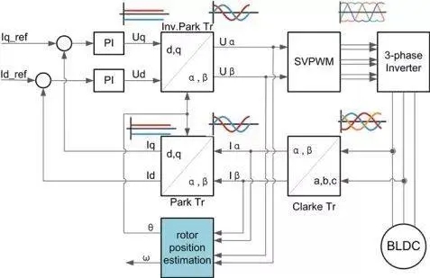
FOC can be divided into sensor FOC and sensorless FOC according to whether the motor has a sensor or not.
For sensored FOC, since the motor's sensor (usually an encoder) can feed back the position information of the motor rotor, the position estimation algorithm can be omitted in the control. The control is relatively simpler than sensorless FOC, but for the application of sensorless motor In other words, it often requires higher control performance.
For sensorless FOC, since the motor does not have any sensor, the position information of the motor rotor cannot be obtained by simply reading the measured value of the sensor. Therefore, it is necessary to collect the motor phase current and use the position estimation algorithm to calculate the rotor position in the control. Although the control of sensorless FOC is more difficult, it can avoid the risk of sensor failure, save the cost of the sensor, and simplify the wiring between the motor and the drive board. At present, non-inductive FOC is mostly used in fan applications.
-
The principle and application field of Autonics panel products (handling)
 June 12, 2021
 -
New product launch SRH1 series single-phase SSR with integrated heat sink
 June 12, 2021
 -
New product launch SRH1 series single-phase SSR with integrated heat sink
 June 12, 2021
 -
Otto protection grade IP69K new product launched Ø18mm cylindrical (SUS316L housing) photoelectric sensor BRQT series
 June 12, 2021
 -
Autonics adds shading motion mode sensor
 June 12, 2021