Application of photoelectric encoder in motor control system
Application of photoelectric encoder in motor control system
Overview: Motor position detection is very important in motor control, especially in applications where the motor's motion state needs to be controlled based on the precise rotor position, such as a position servo system. The position detection in the motor control system usually includes: micro-motor solving components, photoelectric components, magnetic sensitive components, electromagnetic induction components, etc. These position detection sensors are either coaxially connected with the non-load end of the motor, or directly installed in a specific part of the motor. Among them, the measurement accuracy of the photoelectric element is relatively high, and it can accurately reflect the mechanical position of the rotor of the motor, thereby indirectly reflecting the accurate mechanical position of the mechanical load connected to the motor, so as to achieve the purpose of accurately controlling the position of the motor. In this article, I will mainly introduce the internal structure, working principle and position detection method of the high-precision photoelectric encoder.
1. Introduction of photoelectric encoder:
The photoelectric encoder expresses the position information of the motor rotor connected to the photoelectric encoder by reading the pattern or code information on the photoelectric encoder disc. According to the working principle of the photoelectric encoder, the photoelectric encoder can be divided into an absolute photoelectric encoder and an incremental photoelectric encoder. Below, I will introduce the structure and working principle of these two photoelectric encoders.
(1) Absolute photoelectric encoder
The absolute photoelectric encoder is shown in the figure. It expresses the absolute position information by reading the binary coded information on the code disc.
The encoding disc is a disc made according to a certain encoding form. Figure 1 is a binary coded disc. The blank part in the figure is transparent and is represented by "0"; the black part is opaque and represented by "1". The circles that make up the code are usually called code channels. Each code channel represents one bit of a binary number. The outermost bit is the lowest bit, and the innermost bit is the highest bit. If the code disc has 4 code tracks, the code tracks from the inside to the outside are expressed as binary 23, 22, 21 and 20 respectively. 4 binary numbers can form 16 binary numbers, so the disc is divided into 16 sectors , Each sector corresponds to a 4-bit binary number, such as 0000, 0001,..., 1111.
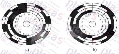
Configure the corresponding photoelectric sensor according to the code track formed on the code disc, including the light source, lens, code disc, photodiode and driving electronic circuit. When the code wheel rotates to a certain angle, the photodiode corresponding to the light-transmitting code channel in the sector is turned on and outputs a low level "0", and the photodiode corresponding to the light-shielding code channel is not conductive and outputs a high level " 1", in this way, the high and low level output consistent with the encoding mode is formed, thereby obtaining the position pin of the sector.
(Two), incremental photoelectric encoder
Incremental photoelectric encoder is a code disc that outputs a series of pulse signals with the change of position, and then uses a counter to count up/down the pulse according to the direction of position change, so as to achieve the purpose of position detection. It is composed of light source, lens, main grating code disc, discriminating disc, photosensitive element and electronic circuit.
The working principle of the incremental photoelectric encoder is that the main grating code disc with uniform narrow slits in the radial direction is driven by the rotation of the rotating shaft. On the main grating code disc, there is a discriminating disc parallel to it, on the discriminating disc There are two narrow slits with a phase shift of 90° from each other, and a photodiode respectively receives the signal transmitted by the main grating code disk. When working, the discriminator disc does not move, the main grating code disc rotates with the rotor, the light source is directed parallel to the main grating code disc through the lens, and the photodiode receives an approximately sinusoidal signal with a phase difference of 90o after passing through the main grating code disc and discriminating disc. Then the logic circuit forms the turn signal and count pulse signal. In order to obtain the absolute position angle, there is a zero pulse in the incremental photoelectric encoder, that is, every time the main grating rotates a circle, a zero pulse is output to clear the position angle. The position and speed of the motor can be detected by the incremental photoelectric encoder.
2. Measuring method of photoelectric encoder:
The photoelectric encoder can be used to measure the magnetic field position and mechanical position of the motor rotor and the change speed and direction of the magnetic field and mechanical position of the rotor in motor control. Let me introduce the application methods of photoelectric encoder in these aspects.
(1) Use a photoelectric encoder to measure the speed of the motor
You can use the timer/counter with the output pulse signal of the photoelectric encoder to measure the motor speed. There are three specific speed measurement methods: M method, T method and M/T method.
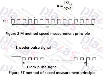
The M method is also called the frequency measurement method. The principle of speed measurement is to count the pulse signals output by the photoelectric encoder within the specified detection time Tc. As shown in Figure 2, for example, the photoelectric encoder is N-line. Then there can be 4N pulses per revolution, because the rising and falling edges of the two pulses just double the frequency of the encoder signal. Now suppose that the detection time is Tc and the number of pulses recorded by the counter is M1, then the speed of the motor per minute is
In the actual measurement, the number of pulses within the time Tc may not be exactly an integer, and there is a maximum error of half a pulse. If the required measurement error is less than the specified range, for example, less than one percent, then M1 should be greater than 50. At a certain speed, the number of detection pulses M1 should be increased to reduce the error. The detection time Tc can be increased. Considering the actual application detection time is very short, for example, the measurement speed in the servo system is used for feedback control, generally should be 0.01 Less than seconds. It can be seen that the method to reduce the measurement error is to use a photoelectric encoder with a high number of lines.
The M method is suitable for measuring high speed, because for a given photoelectric encoder line number N machine measuring time Tc, the higher the speed, the larger the count pulse M1 and the smaller the error.
The T method is also called the weekly measurement method. The speed measurement method is a method of counting the clock signal pulses within a pulse period, as shown in Figure 3. For example, the clock frequency is fclk, the number of pulses recorded by the counter is M2, the photoelectric encoder is N-line, and each line outputs 4N pulses, then the motor's speed per minute is
In order to reduce the error, it is desirable to record as many pulses as possible, so the T method is suitable for low-speed running occasions. But the speed is too low, an encoder output pulse time is too long, the number of clock pulses will exceed the counter maximum count value and overflow; in addition, the time is too long will also affect the speed of control. Like the M method for speed measurement, choosing a photoelectric encoder with more lines can improve the speed and accuracy of motor speed measurement.
The M/T method speed measurement is a combination of the M method and the T method. In a certain time range, the number of pulses M1 and M2 output by the photoelectric encoder are counted at the same time, and the motor speed per minute is
In actual work, count the pulses of the photoelectric encoder within a fixed Tc time, start timing at the rising edge of the first photoelectric encoder, and start recording the number of photoelectric encoder and clock pulses at the same time, the timer timing Tc time is up, Stop counting the pulses of the photoelectric encoder, and the clock pulse will stop recording when the next rising edge of the photoelectric encoder arrives. The use of M/T method not only has the advantages of high speed of M method speed measurement, but also the advantage of low speed of T method speed measurement. It can cover a wide range of speed and the measurement accuracy is also high. It has a very wide range of applications in motor control.
(2) The principle of using incremental photoelectric encoder to discriminate the direction of motor speed
The incremental photoelectric encoder outputs two pulse signals A and B with a phase difference of 90°. When the motor rotates forward, the phase of the pulse signal A is 90° ahead of the phase of the pulse signal B. At this time, the logic circuit can form a high level Direction signal Dir. When the motor reverses, the phase of the pulse signal A lags the phase of the pulse signal B by 90°. At this time, the direction signal Dir processed by the logic circuit is low. Therefore, the steering of the motor can be determined according to the relationship between lead and lag. The principle of the speed discrimination is shown in Figure 4

Figure 4 Principle diagram of steering discrimination
(3) Quadruple frequency principle of feedback pulse of incremental photoelectric encoder
When using an incremental encoder, the purpose of quadrupling the feedback pulse of the incremental encoder has been achieved by counting the rising and falling edges of the two orthogonal pulse signals A and B with a phase difference of 90°. In this way, without increasing the number of lines of the incremental photoelectric encoder, more precise position pulse information can be obtained to achieve precise control of the motor position. The phase relationship between its working principle and pulse is shown in Figure 5.
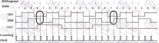
Figure 5 Phase relationship diagram of pulse quadruple frequency
Conclusion:
The photoelectric encoder has good anti-interference characteristics and application reliability, and has broad application prospects in the application environment of motor control with extremely high electromagnetic infection. I believe that the photoelectric encoder will play a more important role in the field of motor control in the near future. And our research on the photoelectric encoder is extremely important.
-
The principle and application field of Autonics panel products (handling)
 June 12, 2021
 -
New product launch SRH1 series single-phase SSR with integrated heat sink
 June 12, 2021
 -
New product launch SRH1 series single-phase SSR with integrated heat sink
 June 12, 2021
 -
Otto protection grade IP69K new product launched Ø18mm cylindrical (SUS316L housing) photoelectric sensor BRQT series
 June 12, 2021
 -
Autonics adds shading motion mode sensor
 June 12, 2021