Basic knowledge of servo system & debugging steps!
Basic knowledge of servo system & debugging steps!
1. Basic knowledge of servo system
1. What is a servo system?
Servomechanism, also known as servo system, is a feedback control system used to accurately follow or reproduce a certain process. The servo system is an automatic control system that enables the output controlled quantity of the object's position, orientation, state, etc. to follow the arbitrary change of the input target (or given value).
Its main task is to amplify, transform and adjust the power according to the requirements of the control command, so that the torque, speed and position control of the drive device is very flexible and convenient. In many cases, the servo system specifically refers to a feedback control system in which the controlled quantity (the output of the system) is mechanical displacement or displacement velocity, acceleration, and its function is to make the output mechanical displacement (or rotation angle) accurately track the input displacement ( Or turning angle), its structure is not different in principle from other forms of feedback control systems.
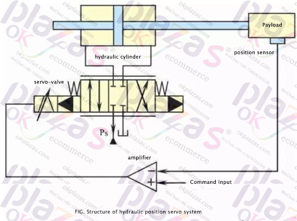
Note: The servo system not only refers to the electrical servo system composed of servo motors, but also the hydraulic servo system composed of servo valves. This article mainly introduces the servo motor system.
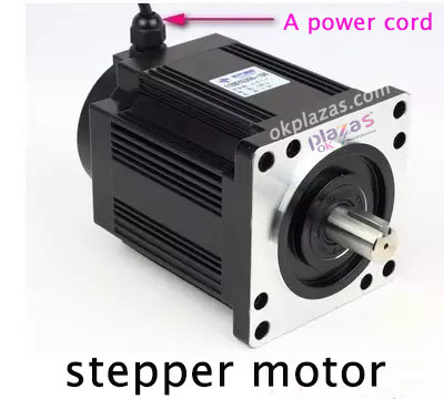
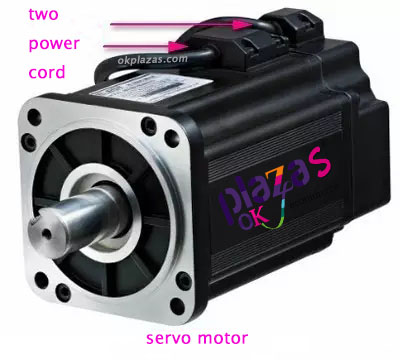
2. What is a servo motor? How is it different from a stepper motor?
Servo motor is also called executive motor. In automatic control system, it is used as an executive element to convert the received electrical signal into angular displacement or angular velocity output on the motor shaft. Divided into two categories: DC and AC servo motors. Its main feature: When the signal voltage is zero, there is no rotation phenomenon, and the speed decreases at a uniform speed with the increase of torque.
The characteristics of the servo points are more clearly explained here compared with the stepper motor:
1. Different control accuracy
The step angle of the two-phase hybrid stepping motor is generally 3.6°, 1.8°, and the step angle of the five-phase hybrid stepping motor is generally 0.72°, 0.36°. There are also some high-performance stepping motors with a smaller step angle. For example, a stepping motor used for slow-moving wire machine tools produced by Stone Company has a step angle of 0.09°; the three-phase hybrid stepping motor produced by Bergerlahr in Germany has a step angle of Code switch settings are 1.8°, 0.9°, 0.72°, 0.36°, 0.18°, 0.09°, 0.072°, 0.036°, which is compatible with the step angle of two-phase and five-phase hybrid stepping motors.
The control accuracy of the AC servo motor is guaranteed by the rotary encoder at the back of the motor shaft. Take Panasonic's all-digital AC servo motor as an example. For a motor with a standard 2500-line encoder, the pulse equivalent is 360°/10000=0.036° due to the quadruple frequency technology used inside the drive. For a motor with a 17-bit encoder, every time the driver receives 217=131072 pulses, the motor makes one revolution, that is, its pulse equivalent is 360°/131072=9.89 seconds. It is 1/655 of the pulse equivalent of a stepping motor with a step angle of 1.8°.
2. Different low frequency characteristics
Stepping motors are prone to low-frequency vibration at low speeds. The vibration frequency is related to the load condition and the performance of the drive. It is generally considered that the vibration frequency is half of the no-load take-off frequency of the motor. This low-frequency vibration phenomenon determined by the working principle of the stepper motor is very unfavorable to the normal operation of the machine. When stepping motors work at low speeds, damping technology should generally be used to overcome low-frequency vibration phenomena, such as adding a damper to the motor, or using subdivision technology on the drive.
The AC servo motor runs very smoothly and there is no vibration even at low speeds. The AC servo system has a resonance suppression function, which can cover the lack of rigidity of the machine, and the internal frequency analysis function (FFT) can detect the resonance point of the machine, which is convenient for system adjustment.
3. Different moment frequency characteristics
The output torque of a stepping motor decreases with the increase of the speed, and will drop sharply at a higher speed, so its maximum working speed is generally 300-600RPM. The AC servo motor has a constant torque output, that is, it can output a rated torque within its rated speed (generally 2000RPM or 3000RPM), and a constant power output above the rated speed.
4. Different overload capacity
Stepper motors generally do not have overload capacity. AC servo motor has strong overload capacity. Take the Panasonic AC servo system as an example, it has speed overload and torque overload capabilities. The maximum torque is three times the rated torque, which can be used to overcome the moment of inertia of the inertial load at the moment of starting. Because stepper motors do not have this overload capacity, in order to overcome this moment of inertia when selecting models, it is often necessary to select a motor with a larger torque, and the machine does not need such a large torque during normal operation, so a torque appears. The phenomenon of waste.
5. Different operating performance
Stepper motor control is open loop control. If the starting frequency is too high or the load is too large, it is easy to lose steps or stall. When the speed is too high, it is easy to overshoot. Therefore, to ensure its control accuracy, it should be handled well. Increase and decrease speed problems. The AC servo drive system is a closed-loop control. The drive can directly sample the feedback signal of the motor encoder. The position loop and speed loop are formed inside. Generally, stepping motors will not lose steps or overshoot, and the control performance is more reliable.
6. Different speed response performance
It takes 200 to 400 milliseconds for a stepping motor to accelerate from a standstill to a working speed (generally several hundred revolutions per minute). The acceleration performance of the AC servo system is better. Take the Panasonic MSMA400W AC servo motor as an example. It only takes a few milliseconds to accelerate from a standstill to its rated speed of 3000RPM, which can be used in control situations that require fast start and stop.
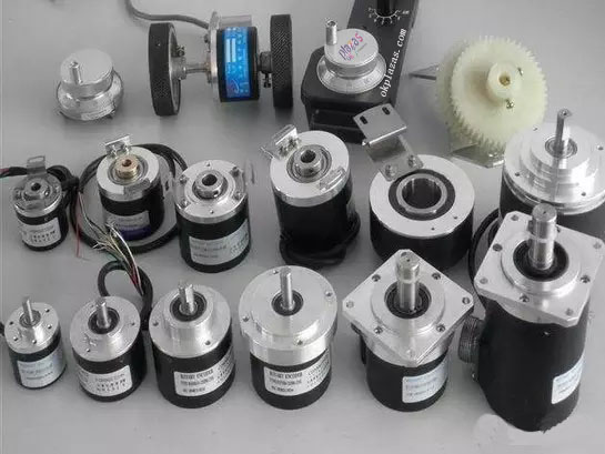
3. What is an encoder? What are the types?
An encoder is a device that compiles and converts a signal (such as a bit stream) or data into a signal form that can be used for communication, transmission and storage. The encoder converts angular displacement or linear displacement into electrical signals. The former is called a code wheel and the latter is called a code ruler.
It is a signal feedback component. Encoders can be classified in the following ways.
1. According to the different classification of code discs
(1)Incremental type: it sends out a pulse signal every time a unit of angle is rotated (also sends out sine and cosine signals, then subdivides them, and chops them to produce higher frequency pulses), usually phase A and phase B , Z phase output, A phase and B phase are mutually delayed by 1/4 cycle pulse output. According to the delay relationship, the forward and reverse can be distinguished, and the frequency can be doubled or 4 times by taking the rising and falling edges of A and B ; Phase Z is a single-turn pulse, that is, one pulse is sent out every turn.
(2) Absolute value type: it corresponds to a circle, and each reference angle emits a unique binary value corresponding to the angle, and the recording and measurement of multiple positions can be performed through an external circle device.
2. Classified by signal output type
It can be divided into: voltage output, open collector output, push-pull complementary output and long-line drive output.
3. Classified by encoder mechanical installation form
(1) Shaft type: Shaft type can be divided into clamping flange type, synchronous flange type and servo mounting type.
(2) Bushing type: The bushing type can be divided into half hollow type, full hollow type and large diameter type etc.
4. Classification according to the working principle of the encoder
Can be divided into: photoelectric type, magnetoelectric type and contact brush type.
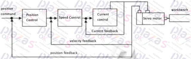
4. How to realize servo control?
1. Servo is mainly based on pulses for positioning. Basically, it can be understood that when the servo motor receives 1 pulse, it will rotate the angle corresponding to 1 pulse to achieve displacement. Because the servo motor itself has the function of sending pulses, so the servo Each time the motor rotates one angle, a corresponding number of pulses will be sent out. In this way, it corresponds to the pulse received by the servo motor, or is called a closed loop. In this way, the system will know how many pulses have been sent to the servo motor and how many have been received The pulse returns, so that the rotation of the motor can be controlled very accurately, so as to achieve precise positioning, which can reach 0.001mm.
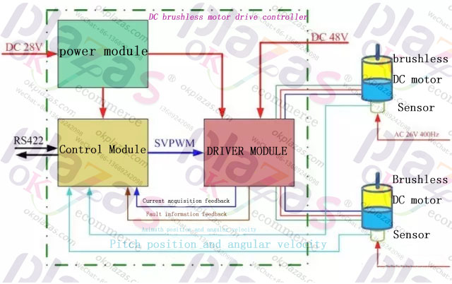
DC servo motors are divided into brush and brushless motors. The brush motor has low cost, simple structure, large starting torque, wide speed range, easy control, and needs maintenance, but it is easy to maintain (change carbon brushes), generate electromagnetic interference, and have requirements for the environment. Therefore, it can be used in common industrial and civil applications that are sensitive to cost.
The brushless motor is small in size, light in weight, large in output, fast in response, high in speed, small inertia, smooth in rotation and stable in torque. The control is complicated and it is easy to realize intelligence. Its electronic commutation method is flexible, and it can be square wave commutation or sine wave commutation. The motor is maintenance-free, highly efficient, low operating temperature, low electromagnetic radiation, long life, and can be used in various environments.
2. AC servo motors are also brushless motors, which are divided into synchronous and asynchronous motors. At present, synchronous motors are generally used in motion control. It has a large power range and can achieve a large power. Large inertia, low maximum rotation speed, and rapid decrease as the power increases. Therefore, it is suitable for low-speed and smooth running applications.
3. The rotor inside the servo motor is a permanent magnet. The U/V/W three-phase electricity controlled by the driver forms an electromagnetic field. The rotor rotates under the action of this magnetic field. At the same time, the encoder of the motor feeds back the signal to the driver, and the driver according to the feedback value Compare with the target value and adjust the angle of rotor rotation. The accuracy of the servo motor is determined by the accuracy of the encoder (number of lines).
Two, debugging steps
1. Initialization parameters
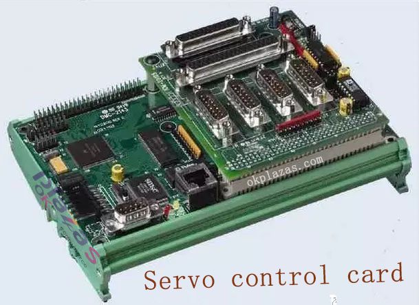
Before wiring, initialize the parameters. On the control card: select the control mode; clear the PID parameters; let the default enable signal turn off when the control card is powered on; save this state to ensure that the control card is in this state when it is powered on again.
On the servo motor: set the control mode; set the enable to be controlled externally; set the gear ratio of the encoder signal output; set the proportional relationship between the control signal and the motor speed. Generally speaking, it is recommended that the maximum design speed in servo work corresponds to a control voltage of 9V.
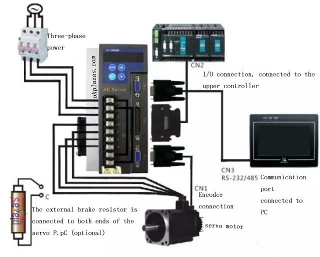
2. Wiring
Power off the control card and connect the signal line between the control card and the servo. The following lines must be connected: the analog output line of the control card, the enable signal line, and the encoder signal line of the servo output. After rechecking the wiring for no errors, power on the servo motor and control card (and PC). At this time, the motor should not move, and it can be easily rotated with external force. If not, check the setting and wiring of the enable signal. Rotate the motor with external force and check whether the control card can correctly detect the change of the motor position, otherwise check the wiring and setting of the encoder signal.
3. Try the direction
For a closed-loop control system, if the direction of the feedback signal is not correct, the consequences must be catastrophic. Turn on the enable signal of the servo through the control card. This is the servo should rotate at a lower speed, which is the legendary "zero drift". Generally, there will be instructions or parameters to suppress zero drift on the control card. Use this command or parameter to see if the motor speed and direction can be controlled by this command (parameter).
If it cannot be controlled, check the analog wiring and the parameter settings of the control mode. Confirm that a positive number is given, the motor rotates forward, and the encoder count increases; when a negative number is given, the motor rotates backward, and the encoder count decreases. If the motor is loaded with a limited stroke, do not use this method. Do not give too much voltage to the test, it is recommended to be below 1V. If the directions are inconsistent, you can modify the parameters on the control card or the motor to make them consistent.
4. Suppress zero drift
In the closed-loop control process, the existence of zero drift will have a certain impact on the control effect, and it is best to suppress it. Use control card or servo parameters to suppress zero drift, and carefully adjust to make the motor speed approach zero. Since the zero drift itself has a certain degree of randomness, it is unnecessary to require the motor speed to be absolutely zero.
5. Establish closed-loop control
Let go of the servo enable signal through the control card again, and enter a smaller proportional gain on the control card. As for how big it is, it can only be based on feeling. If you are not at ease, enter the smallest allowable control card. value. Turn on the enable signal of the control card and servo. At this time, the motor should be able to roughly act according to the motion command
6. Adjust closed loop parameters
Fine-tune the control parameters to ensure that the motor moves in accordance with the instructions of the control card. This is the work that must be done. This part of the work is more of experience, and can only be omitted here.
-
The principle and application field of Autonics panel products (handling)
 June 12, 2021
 -
New product launch SRH1 series single-phase SSR with integrated heat sink
 June 12, 2021
 -
New product launch SRH1 series single-phase SSR with integrated heat sink
 June 12, 2021
 -
Otto protection grade IP69K new product launched Ø18mm cylindrical (SUS316L housing) photoelectric sensor BRQT series
 June 12, 2021
 -
Autonics adds shading motion mode sensor
 June 12, 2021