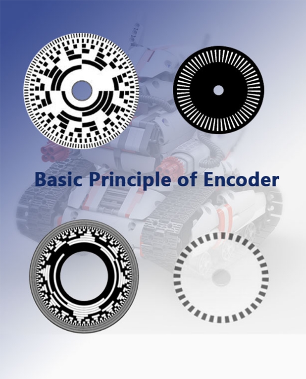
basic principle of encoder
basic principle of encoder
Description
1. There is a 90° phase difference between A and B phases ±1/8T1
2. The zero signal has high and low level selection.
3.UVW signal
It is used to characterize the relationship of 3 signals (electrical angle) with a phase difference of 120°, which is generally used in servo motors.
4. Voltage output
The emitter of the NPN transistor is grounded, and the collector is a circuit with load resistance output.
5. Open collector output
NPN type is a circuit that outputs directly from the collector of a transistor.
6. Long-line driver output
Integrated circuit for long-distance output, the signal is output in positive and negative directions, fast speed, strong anti-interference ability, and it can also detect cable disconnection.
7. Complementary output
The emitter of the NPN type and PNP type pair of tubes is connected to the output circuit. This circuit has a fast response speed and can also be transmitted over long distances.
8. Incremental
A method of outputting pulse trains or periodic trains of sine waves. The position is obtained based on accumulation.
9. Absolute
The method of outputting mechanical displacement using binary code or gray code as absolute position.
10. Positive logic
The symbol "1" is the output logic corresponding to the output voltage "H".
11. Negative logic
The symbol "1" is the output logic corresponding to the output voltage "L".
-
The principle and application field of Autonics panel products (handling)
 June 12, 2021
 -
New product launch SRH1 series single-phase SSR with integrated heat sink
 June 12, 2021
 -
New product launch SRH1 series single-phase SSR with integrated heat sink
 June 12, 2021
 -
Otto protection grade IP69K new product launched Ø18mm cylindrical (SUS316L housing) photoelectric sensor BRQT series
 June 12, 2021
 -
Autonics adds shading motion mode sensor
 June 12, 2021