Design of rotary encoder
Design of rotary encoder
Smart rotary commutation encoder provides output options, simple zero adjustment, simplified BOM and PC-based insights
New methods open up new opportunities
Encoder users have always been reluctant to change, because some innovative motor control technologies that claim to provide excellent performance and reliability must have excellent records and past performance as support before they can be used in workplaces or industrial installations. Although optical encoders and magnetic encoders have a long history and are based on seemingly "more specific" physical concepts, capacitive encoders are also based on thoroughly tested principles and have been successfully applied in the field for many years. prove. This digital alternating method, which is different from motion sensing, provides many benefits and provides a new level of intelligence for designers who utilize rotary encoders.
Rotary encoders are critical to almost all motion-control applications. Due to the increased use of brushless DC motors (BLDC), the demand for rotary encoders is further expanded, and they provide many benefits in terms of control, accuracy, and efficiency. The task of the encoder is very simple. In principle, it is to indicate the position of the motor shaft to the system controller. Please refer to Figure 1. The controller can use this information to accurately and efficiently turn the motor windings and determine the speed, direction and acceleration. These are motions. The control loop maintains the parameters required by the motor performance requirements.
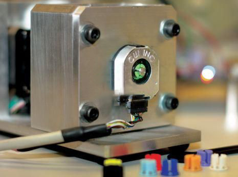
Figure 1 Rotary encoder provides motor shaft direction, position, speed and acceleration information
Encoders can be based on various technologies, these technologies provide standard A and B quadrature signal digital output, some models also provide index output, please refer to Figure 2a. Commutation encoder (more comprehensive description will be provided below) U, V and W commutation-phase channel output, please refer to Figure 2b.
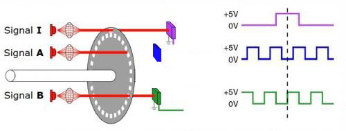
Figure 2a Optical encoder standard A and B quadrature signal and index signal
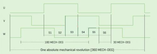
Figure 2b U, V and W waveforms generated by a commutation encoder
Encoder technology
The three most famous encoder methods are based on optical technology, magnetic technology or capacitive technology. In simple terms, optical technology uses a slotted disk with LEDs on one side and phototransistors on the opposite side. When the disc rotates, the optical path is blocked, and the resulting pulse indicates the rotation and direction of the shaft. Although the optical method is cost-effective and efficient, the reliability of optical encoders is reduced by two factors: dirt, dust, grease and other contaminants can interfere with the optical path, and the LED has a limited service life, usually within a few years of its brightness More than half was lost and eventually burned out.
Except for the use of magnetic fields instead of light beams, the structure of magnetic encoders is similar to that of optical encoders. The magnetic encoder uses a disk instead of a grooved optical wheel. The disk rotates on a set of magnetoresistive sensors, which generates a response in these sensors and transmits it to the signal-adjusting front-end circuit to determine the position of the shaft. Although this kind of encoder has high durability, it is susceptible to electromagnetic interference generated by the motor, and its accuracy is not as good as that of an optical encoder.
The third method, the capacitive encoding method, has all the advantages of optical encoders and magnetic encoders, but does not have their disadvantages. This technology uses the same principles as mature, low-cost and precise digital vernier calipers. It has two cylindrical or linear types, one on the fixed element and the other on the moving element. The two together form a variable capacitor configured as a transmitter/receiver pair. Please refer to Figure 3. When the encoder When rotating, the integrated ASIC counts the changes of these lines, and uses interpolation to find the position and rotation direction of the shaft, establishes a standard quadrature output, and the commutation output provided by other encoders for controlling brushless DC (BLDC) motor.
The advantage of this capacitive technology is that it will not wear out and is not affected by pollutants such as dust, dirt and grease that are common in industrial environments, making it inherently more reliable than optical encoders. Capacitive encoders also have the performance advantages brought by their digital control features, including the ability to adjust the encoder's resolution (pulse/revolution), without the need to change to a higher or lower resolution encoder.
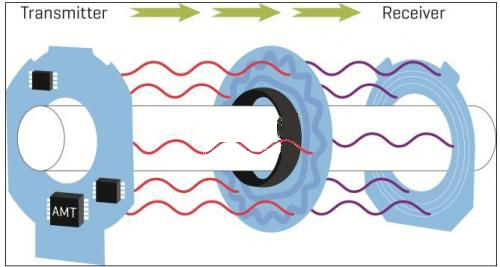
Figure 3 The capacitive encoder counts the received signal modulation pulses sent by the rotor connected to the motor shaft
best choice
CUI's new AMT31 series is a model of advanced capacitive encoders, providing A and B quadrature signals, index signals, and U, V, and W commutation-phase signals. It has 20 optional incremental resolutions between 48-4096 pulses per revolution (PPR), and a total of 7 motor pole-pairs between 2-20. The AMT31 series also has a locking hub to make installation easy. It operates from a 5 V power rail and requires only 16 mA of supply current.
-
The principle and application field of Autonics panel products (handling)
 June 12, 2021
 -
New product launch SRH1 series single-phase SSR with integrated heat sink
 June 12, 2021
 -
New product launch SRH1 series single-phase SSR with integrated heat sink
 June 12, 2021
 -
Otto protection grade IP69K new product launched Ø18mm cylindrical (SUS316L housing) photoelectric sensor BRQT series
 June 12, 2021
 -
Autonics adds shading motion mode sensor
 June 12, 2021