Diagram of connection method of proximity switch with shielded wire
Diagram of connection method of proximity switch with shielded wire
Diagram of connection method of proximity switch with shielded wire
Proximity switch is a position switch that can be operated without direct mechanical contact with moving parts. When an object approaches the sensing surface of the switch to the operating distance, it does not require mechanical contact or any pressure to make the switch act, thereby driving DC electrical appliances. Or provide control instructions to the computer (PLC) device. Proximity switch is a kind of switch type sensor (namely non-contact switch). It has the characteristics of travel switch and micro switch, and has sensing performance, reliable action, stable performance, fast frequency response, long application life and anti-interference. Strong ability, and has the characteristics of waterproof, shockproof, corrosion resistance and so on. Products are inductive, capacitive, Hall, AC and DC.
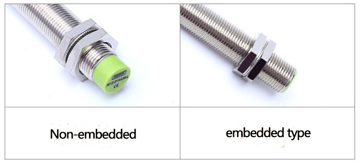
The tail of the conventional proximity switch is connected by a circular link (that is, the proximity switch connection line). This circular connector is M12*1, M8*1 is the main one, and the cable length is 2M, 5M, or 10M.
Proximity switches can be used for in-position detection or limit detection. In some places where the environment is relatively harsh, there is a shielding layer on the leads. The shielding layer is a metal mesh braided layer. The shielding layer wraps the signal line to prevent signal interference. For the purpose, the braid is generally red copper or tinned copper. When wiring, connect the shielding layer to the ground to transmit interference signals to the ground. Proximity switches are generally divided into NPN type and PNP type. The output signal is the open collector output of the triode, with or without shielding layer does not affect its wiring method. The wiring method of NPN and PNP type proximity switches is introduced below. ,
Wiring method of NPN type proximity switch with shielding layer
When connecting the NPN proximity switch and the plc, a resistor needs to be used to pull the output signal out to the power supply, the power supply is used as the common terminal, and the output terminal out is connected to the PLC, as shown in the figure below.
The shielding layer should be connected to the shell or the ground. When there is no signal in place in the above figure, the transistor is not conducting, and out outputs a high level. When in place, the transistor is turned on and out outputs a low level.
Wiring method of PNP type proximity switch with shielding layer
When the PNP proximity switch is connected to the PLC, a resistor needs to be used to pull the output signal out to GND, and GND is used as the common terminal, and the output terminal out is connected to the PLC, as shown in the figure below.
The shielding layer should be connected to the shell or the ground. When there is no signal in place in the above figure, the transistor is not conducting and out outputs low level. When in place, the transistor is turned on and out outputs a high level.
In the above two wiring methods, the shielding layer is connected to the shell or the ground, and the interference signal is introduced into the ground to reduce the interference to the signal and improve the working stability of the sensor.
The above is the wiring method of the proximity switch with shielding layer
-
The principle and application field of Autonics panel products (handling)
 June 12, 2021
 -
New product launch SRH1 series single-phase SSR with integrated heat sink
 June 12, 2021
 -
New product launch SRH1 series single-phase SSR with integrated heat sink
 June 12, 2021
 -
Otto protection grade IP69K new product launched Ø18mm cylindrical (SUS316L housing) photoelectric sensor BRQT series
 June 12, 2021
 -
Autonics adds shading motion mode sensor
 June 12, 2021