Dry goods encoder principle, line number, resolution concept, and encoder wiring method
Dry goods encoder principle, line number, resolution concept, and encoder wiring method
Dry goods encoder principle, line number, resolution concept, and encoder wiring method
Encoders are very common in engineering applications, such as the use of servo motors for positioning control, etc., and encoders play a decisive role in them. Today I will analyze what an encoder is, and the classification and how of the encoder. application.
What is an encoder?
Encoder is a device that compiles and converts signals or data into signal forms that can be used for communication, transmission and storage. The encoder converts angular displacement or linear displacement into electrical signals. The former is called a code wheel and the latter is called a code ruler. It is a commonly used motor positioning device in the industry, which can accurately test the angular displacement and rotation position of the motor.
How to understand the concept of encoder resolution?
How to understand the resolution of the encoder? Common encoder types include absolute encoders and incremental encoders. You should be clear about the concept of absolute and incremental. The biggest difference is that the absolute position is memorized and the encoder rotates. Each scale is marked, and the position can be remembered after the power is turned off and on again, and the incremental type is a technology that counts as many rotations as possible, and the position is not remembered after the power is turned off. The encoder and motor can be used in angle, length measurement, speed measurement, positioning and other occasions./p>
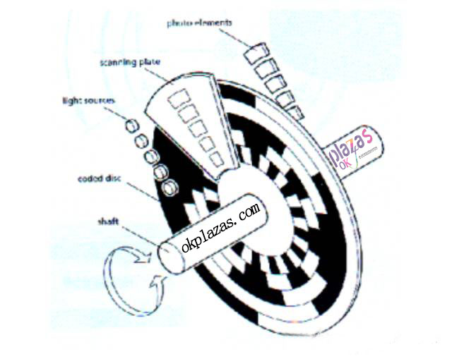
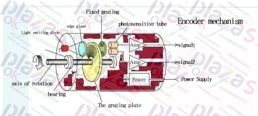
The structure diagram of the encoding is as follows. The measurement principle is not mentioned here, but the resolution is mainly discussed. When we get an encoder, we can see that the unit is P/R, ppr (pulse per revolution), and the encoder behind the servo motor is still There are 1000 lines, 2500 lines; 15-bit, 16-bit and other unit resolution, it is easy to confuse. Regardless of the unit, what we ultimately need to know is how many pulses the encoder outputs per revolution. Common encoder output signals are ABZ three-phase, of which AB phase is the pulse output signal, Z phase is the number of turns, and the phase difference of AB is 90°. The direction of rotation is judged according to whether A leads B or lags B.
First of all, let's see that P/R and ppr refer to the number of pulses in one revolution. This is very simple and clear and can be understood. Look at the offline unit:
Encoder's photoelectric code disc's one-week marking, incremental code disc marking can be 10 lines, 100 lines, 2500 lines, as long as your code disc can engrave, the encoder can distinguish the angle, for general calculation Calculated by 360 degrees/number of reticles.
According to the above explanation, how many copies of the encoder photoelectric code disc are divided into one circle can also be understood as how many pulses are converted into one circle, but when counting pulses, the method of 4 times frequency is often used to count, so that the resolution is adjusted. It is 4 times higher. For example, the resolution of a 2500-line encoder is 10000p/r. How to understand the difference between 4 times frequency and 1 times frequency, let's illustrate with the following figure pulse square wave:
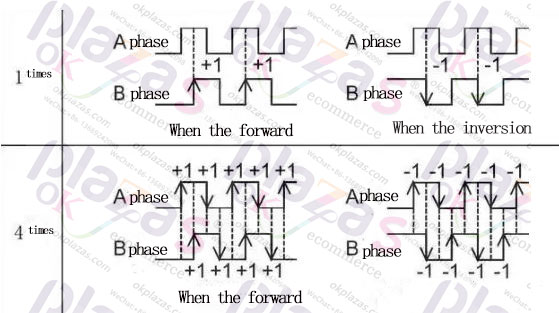
In simple terms, 1 frequency multiplication count is to completely detect a cycle of A and B square waves and output a pulse. 4 frequency multiplication is to detect 1 rising edge, 1 falling edge of A and 1 rising edge of B in one cycle. 1 falling edge, each rising or falling edge outputs a pulse, so that 4 pulses are output in one cycle, so the resolution is improved and the positioning is accurate.
The concept of bits comes from the absolute encoder:
There are several concentric code discs along the radial direction on its circular code disc. Each track consists of light-transmissive and opaque sectors. The number of sectors of adjacent code tracks is doubled. The number of code channels is the number of binary digits. On one side of the code wheel is the light source, and on the other side there is a photosensitive element corresponding to each code channel. When the code wheel is in different positions, each photosensitive element is switched according to whether it receives light or not. Output the corresponding level signal to form a binary number and output it to the power of 2 to the power of n.
For example, the 15th and 17th powers of 2 subdivide the code disc. Note that the concept of line is converted into p/r. The unit has not been subdivided by frequency multiplication, and the 15 and 17 bits are subdivided. It can be seen that generally the resolution with "bit" as the unit is higher than the line, and the resolution of more than 1000 lines in the encoder is often expressed in bits.
After the above description, do you know the resolution of the encoder?
Correct wiring method of encoder:
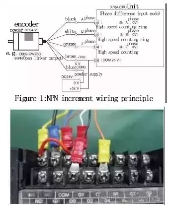
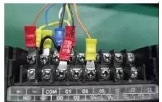
(1)Correct wiring is essential. Figure 1 shows the wiring principle of NPN output incremental E6B2-CWZ6C. Figure 2 shows the actual wiring of NPN output incremental E6B2-CWZ6C. The brown wire is connected to the positive pole of the power supply and the blue wire is connected The negative of the power supply, the black wire is connected to the input 0.00, the white wire is connected to the input 0.01, the orange wire is connected to the input 0.04, and the COM of the PLC is connected to the positive power supply.
(2)The figure below is the actual wiring diagram of the PNP output incremental E6B2-CWZ6B. The brown wire is connected to the positive pole of the power supply, the blue wire is connected to the negative pole of the power supply, the black wire is connected to the input 0.00, the white wire is connected to the input 0.01, and the orange wire is connected to the input 0.04. The COM of the PLC is connected to the negative pole of the power supply.
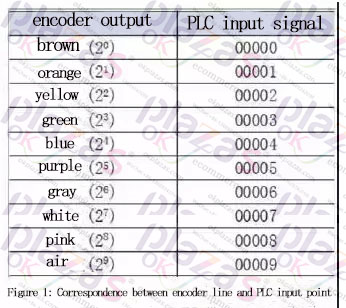
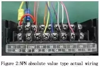
(3)Figure 1 is the corresponding diagram of the absolute value encoder line and the PLC input point, Figure 2 is the actual wiring diagram of the NPN output absolute value E6C3-AG5C, the red line is connected to the positive pole of the power supply, and the black line is connected to the negative pole of the power supply. Brown wire to input 0.00, orange wire to input 0.01, yellow wire to input 0.02, green wire to input 0.03, blue wire to input 0.04, purple wire to input 0.05, gray wire to input 0.06, white wire to input 0.07, pink Wire input is 0.08, and PLC COM is connected to the positive pole of the power supply.
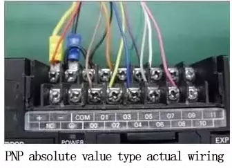
(4)The figure below is the actual wiring diagram of PNP output absolute value type E6C3-AG5B, the red wire is connected to the positive pole of the power supply, the black wire is connected to the negative pole of the power supply, the brown wire is connected to the input 0.00, the orange wire is connected to the input 0.01, the yellow wire is connected to the input 0.02, green The wire is connected to input 0.03, the blue wire is connected to input 0.04, the purple wire is connected to input 0.05, the gray wire is connected to input 0.06, the white wire is connected to input 0.07, the pink wire is connected to input 0.08, and the COM of the PLC is connected to the negative pole of the power supply.
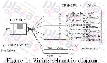
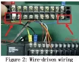
(5)Figure 1 is the wiring principle of the line drive encoder, Figure 2 is the actual wiring diagram, the black wire is connected to A0+, the black and red border wire A0-, the white wire is connected to B0+, the white and red border wire is connected to B0-, and the orange wire is connected to Z0+ , The orange-red fringe wire is connected to Z0-, the brown wire is connected to the power supply +5V, and the blue wire is connected to the power supply 0V. Do not wire it wrongly.
The number of encoder lines is the resolution, the number of pulses per revolution, from incremental encoder to absolute encoder
The rotary incremental encoder outputs pulses when rotating, and calculates its position through the counting device. When the encoder does not move
Or when the power fails, rely on the internal memory of the counting device to remember the position. In this way, when the power is off, the encoder cannot move. When the power is applied, the encoder cannot lose the pulse due to interference during the pulse output. Otherwise, the zero point calculated and memorized by the counting device will shift, and this The amount of this offset is impossible to know, only after the wrong production results appear.
The solution is to increase the reference point. Every time the encoder passes the reference point, the reference position is corrected into the memory position of the counting device. Before the reference point, the accuracy of the position cannot be guaranteed. For this reason, in industrial control, there are methods such as first finding the reference point for each operation, turning on the machine, and so on.
This method is more troublesome for some industrial control projects, and it is not even allowed to turn on change (you must know the exact position after turning on), so there is an absolute encoder.
There are many optical channel engraved lines on the optical code disc of absolute encoder, and each engraved line is sequentially divided into 2 lines, 4 lines, 8 lines and 16 lines. . . . . . Arrangement, in this way, at each position of the encoder, by reading the open and dark of each engraved line, a set of unique binary codes from the zero power of 2 to the n-1 power of 2 (Gray Code), which is called an n-bit absolute encoder. Such an encoder is determined by the mechanical position of the photoelectric code disc, and it is not affected by power failure or interference. Each position determined by the mechanical position of the absolute encoder is unique. It does not need to be memorized, does not need to find a reference point, and does not need to be counted all the time. When it needs to know the position, when to read its position. In this way, the anti-interference characteristics of the encoder and the reliability of the data are greatly improved.
From single-turn absolute encoder to multi-turn absolute encoder
Rotate a single-turn absolute encoder to measure each engraved line of the photoelectric code disk during rotation to obtain a unique code. When the rotation exceeds 360 degrees, the code returns to the original point, which does not comply with the absolute code unique principle. The encoding can only be used for measurement within 360 degrees of rotation, which is called a single-turn absolute encoder. If you want to measure rotation beyond 360 degrees, you must use a multi-turn absolute encoder. The encoder manufacturer uses the principle of clock gear mechanism. When the center code wheel rotates, another set of code discs (or multiple sets of gears, multiple sets of code discs) are driven by gears, and the number of turns is added to the single-turn encoding. Encoding, in order to expand the measuring range of the encoder, such an absolute encoder is called a multi-turn absolute encoder, it is also determined by the mechanical position code, each position code is unique and does not repeat, without the need to remember.
Another advantage of multi-turn encoders is that due to the large measurement range, they are often richer in actual use. Generally, multi-turn absolute encoders should use communication transmission for large data volume.
Now , you know about the encoder, don’t be unfamiliar anymore , if you don’t understand, you can leave us a message, solve what you can’t, let us help the healthy development of the industry together!
-
The principle and application field of Autonics panel products (handling)
 June 12, 2021
 -
New product launch SRH1 series single-phase SSR with integrated heat sink
 June 12, 2021
 -
New product launch SRH1 series single-phase SSR with integrated heat sink
 June 12, 2021
 -
Otto protection grade IP69K new product launched Ø18mm cylindrical (SUS316L housing) photoelectric sensor BRQT series
 June 12, 2021
 -
Autonics adds shading motion mode sensor
 June 12, 2021