eltra encoder EMD signal selector
eltra encoder EMD signal selector
eltra encoder EMD signal selector
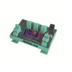
EMD signal selector is used in applications where it is necessary to select an available signal from the signals of up to three encoders. The input signal received by the EMD signal selector comes from the signals of up to three encoders, and this signal is the electronic output signal.
The output signal of the encoder is selected by different combinations of the logic states of ini and in2 on the X5 terminal board or the state of the F1, F2, and F3 relay contacts.
The output mode of the encoder selected by the EMD signal selector must be consistent with the output mode of the input signal described by the EMD signal selector. Its output terminal and the electrical signal output mode of the connected encoder must be specified in the order code, and there are One condition, the electrical signal output mode of the three selected encoders must be the same. In addition, the contacts provided by the EMD signal selector are usually open. When a certain encoder is selected, the corresponding contact is closed.
In order to better understand the use of EMD board, give an example:
We need to read the signals of three encoders (or other compatible sensors) through an instrument; the output mode of these three encoders is the same, such as 5VDC long-line drive. However, the instrument that collects data may adopt other electronic output methods, such as 24VDC push-pull type, and cannot read 5VDC long-line drive. In this case, the EMD signal selector can be used to switch the encoder output mode, and the switched encoder output mode is configured according to the requirements of the instrument.
The order code is: EMD5L8/24P
Among them, 5L indicates that the input is a 5VDC long-line drive encoder, 8/24P indicates that the output is a push-pull electrical output mode, and the power supply is 8 to 24VDC.
The supply voltage of the EMD board must be the highest voltage among the required line voltages; in this example it is 8/24dc. The mutual switching of encoders is realized by adding a logic command to the IN1 and IN2 input terminals of the Xn5 terminal board.
The above-mentioned input terminal is connected to a voltage between ten 5 and ten 24 VDC to obtain a logic level "1'"; while at the level of '0', the voltage must be between 0 and ten 3 VDC. The different combinations of logic levels on IN1 and IN2 can configure the output terminal board into the four modes described in the table.
-
The principle and application field of Autonics panel products (handling)
 June 12, 2021
 -
New product launch SRH1 series single-phase SSR with integrated heat sink
 June 12, 2021
 -
New product launch SRH1 series single-phase SSR with integrated heat sink
 June 12, 2021
 -
Otto protection grade IP69K new product launched Ø18mm cylindrical (SUS316L housing) photoelectric sensor BRQT series
 June 12, 2021
 -
Autonics adds shading motion mode sensor
 June 12, 2021