Encoder diagram
Encoder diagram
Encoder diagram
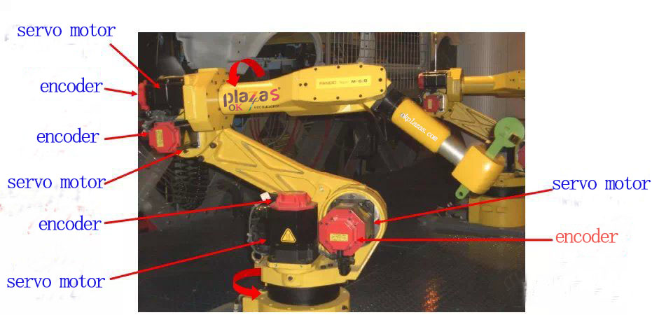
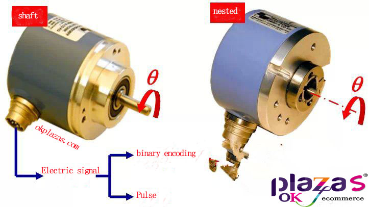
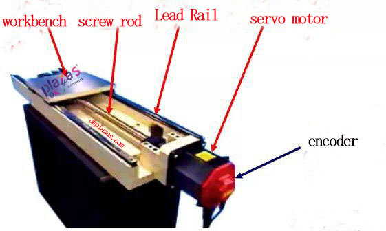
1.Know the encoder (application of encoder in robot control)
2.Measuring object of encoder
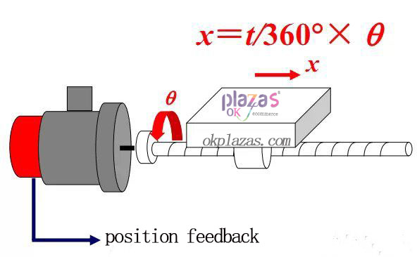
3. The way the encoder measures the linear displacement
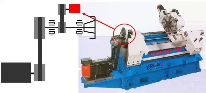
(1) The encoder is installed at the end of the screw
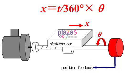
By measuring the angular displacement q of the ball screw, the linear displacement x of the worktable is indirectly obtained, forming a position semi-closed-loop servo system.
(2)Lead screw pitch
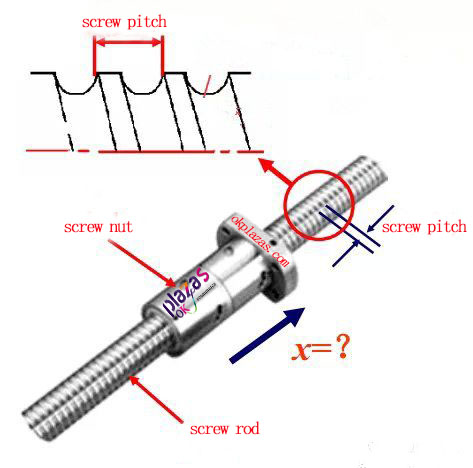
Suppose: the thread pitch t=4mm, the lead screw rotates 10 times in 4s, and find: the average speed of the lead screw n (r/min) and how many millimeters does the nut move? What is the average speed v of the nut moving?
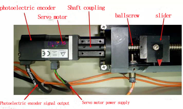
(3)Coaxial installation of encoder and servo motor
(4)Coaxial installation of encoder and servo motor
(5)Coaxial installation of encoder and servo motor
(6)Comparison of two installation methods of encoder
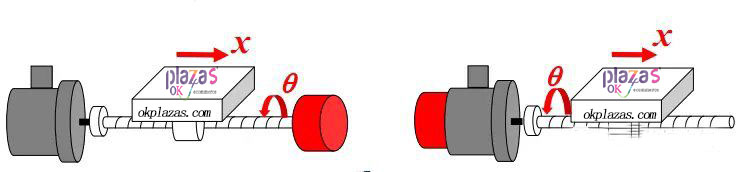
What is the difference in position control accuracy between the encoder installed at the end of the lead screw and the front end (coaxial with the servo motor)?
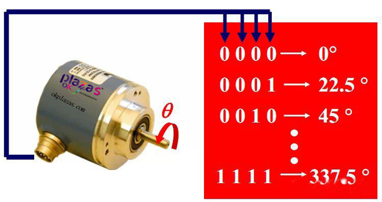
4. Absolute measurement (ABS)
(1) Signal nature
Output n-bit binary code, each code corresponds to a unique angle.
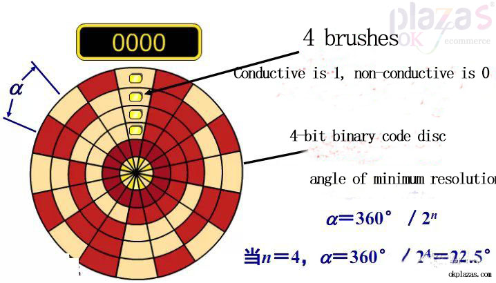
(2)Contact absolute code disc
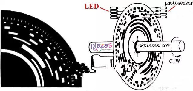
(3)Absolute optical encoder
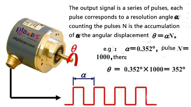
5 Incremental measurement (INC)
(1)Signal nature
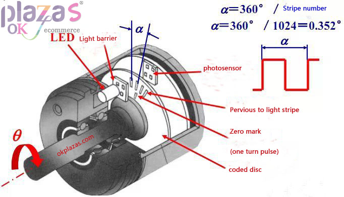
(2)Structure of incremental photoelectric encoder
(3)Identification
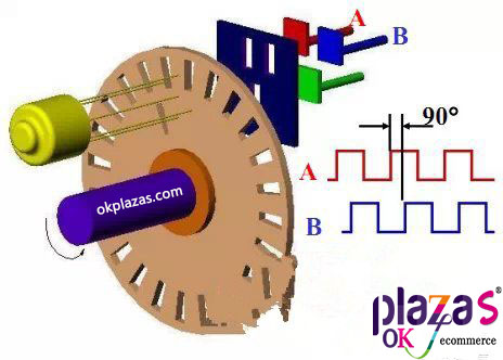
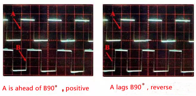
The signals A and B generated by the photosensitive element are 90° out of phase with each other and are used for direction identification. When the code wheel is rotating forward, the A signal leads the B signal by 0°; when the code wheel is reversed, the B signal leads the A signal by 90°.
(4)Direction identification signal
(5)Frequency multiplication (subdivision)
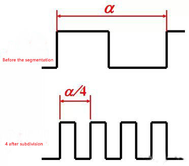
Under the condition of the existing encoder, the resolution of the encoder can be improved through the subdivision technology. Before subdivision, the resolution of the encoder is only the size of a resolution angle. After adopting 4 subdivision technology, the frequency of counting pulse is increased by 4 times, which is equivalent to increasing the resolution of the original encoder by 3 times, and the measurement resolution angle is 1/4 of the original, which improves the measurement accuracy.
(6)Zero mark (one revolution pulse)
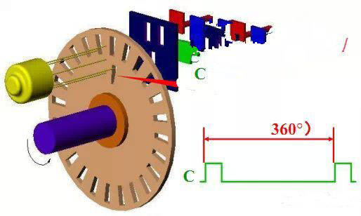
In the circle of the code wheel, there is a slit C, which can generate one pulse per revolution. This pulse signal is also called "one revolution
Signal" or zero mark pulse, as the starting reference for measurement.
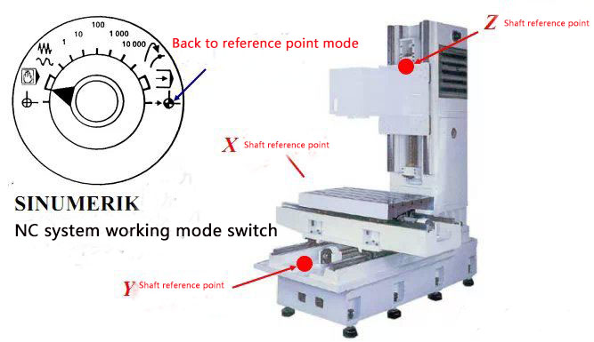
(7)The role of zero mark in returning to reference point
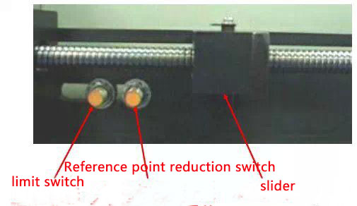
(8)Back to reference point deceleration switch
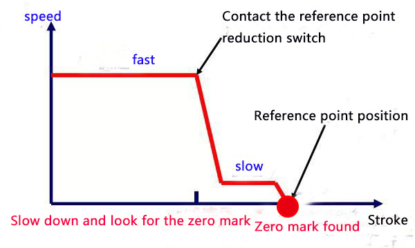
(9)Schematic diagram of returning to reference point
6. Application of encoder in digital speed measurement
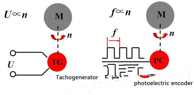
(1)Comparison of analog speed measurement and digital speed measurement
(2)M method speed measurement (suitable for high-speed occasions)
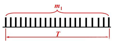
There is an incremental photoelectric encoder whose parameter is 1024p/r, and 65536 pulses are measured in 5s, the speed (r/min) is: n = 60 × 65536 / (1024 × 5) = 768 r/min
The encoder generates N pulses per revolution, and m1 pulses are generated in the T time period, the speed (r/min) is: n = 60m1 / (NT)
(3)T method speed measurement (suitable for low speed occasions)
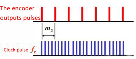
There is an incremental photoelectric encoder with a parameter of 1024p/r, the measured number of pulses between two adjacent pulses is 3000, the clock frequency fc is 1MHz, and the speed (r/min) is:
n = 60fc /(Nm2 )=60×106/(1024×3000)=19.53 r/min
The encoder generates N pulses per revolution, and the known frequency fc is used as the clock. The number of pulses between two adjacent pulses output by the encoder is m2, then the speed (r/min) is: n = 60fc / ( Nm2)
7. Application of encoder in spindle control
(1)Spindle encoder
(2) Spindle encoder is used for C axis control
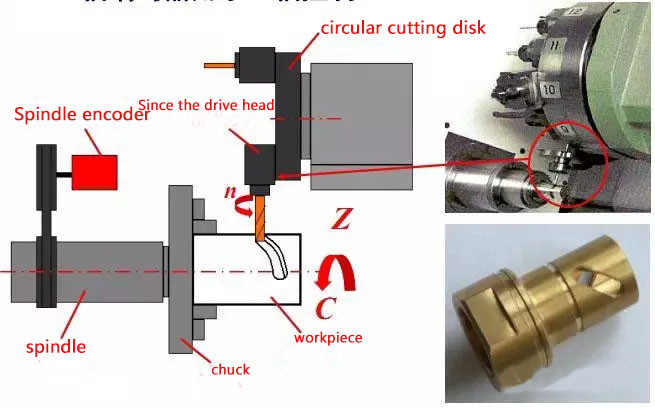
(3) Spindle encoder is used for thread turning
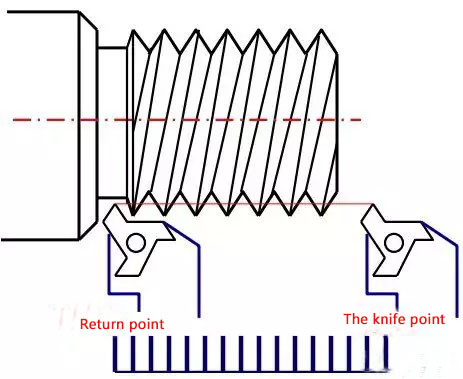
When turning the thread, in order to ensure that the starting point of each cut remains unchanged and to prevent "meshes", the spindle encoder achieves the purpose of thread turning by counting the pulses between the starting point and the retreating point.
8. Summary
1. The encoder is used to measure angular displacement. In the linear feed motion control of CNC machine tools, the linear displacement is indirectly measured by measuring the angular displacement.
2. The absolute encoder outputs binary code, and the incremental encoder outputs pulse.
3. The output signal of the incremental encoder needs to be processed such as direction identification, zero mark and frequency multiplication.
4. Encoder is used for digital speed measurement, with M method and T method, etc.; used for C axis control and thread cutting in CNC lathes.
-
The principle and application field of Autonics panel products (handling)
 June 12, 2021
 -
New product launch SRH1 series single-phase SSR with integrated heat sink
 June 12, 2021
 -
New product launch SRH1 series single-phase SSR with integrated heat sink
 June 12, 2021
 -
Otto protection grade IP69K new product launched Ø18mm cylindrical (SUS316L housing) photoelectric sensor BRQT series
 June 12, 2021
 -
Autonics adds shading motion mode sensor
 June 12, 2021