Encoder wiring specification and 5-wire encoder wiring method
Encoder wiring specification and 5-wire encoder wiring method
Encoder wiring specification
Encoder is a device that compiles and converts physical signals into signals that can be used for communication, transmission and storage. Used in speed control or position control system detection elements. The on-site transportation vehicles all use the CEV65 M type encoder of Dier TR manufacturer, where C means compact absolute, E means optical, V means real axis, M means multi-turn, and 65 means shell 65mm.
Encoder wiring method 1:
Tools needed: a wire stripper, a flat screwdriver with a 2mm opening, a set of six flowers, a pliers with a 3mm opening and a Phillips screwdriver with a 3mm opening
Steps:
1) Set the address, and take the encoder with the wiring port facing down. The left dial is ten digits and the right dial is the ones digit.
2) Set terminal: When only the line is connected, this encoder is the terminal, and both terminals are turned ON; when both the incoming and outgoing lines are connected, both dial codes are dialed to 1.
3) Wiring:
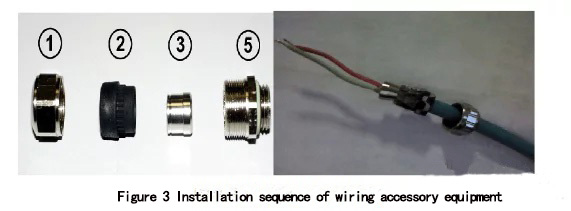
a)Put the accessories of the terminal block on the DP line in order, as shown in Figure 3;
b)Peel off the outer rubber layer of the DP line about 10cm, as shown in Figure 4;
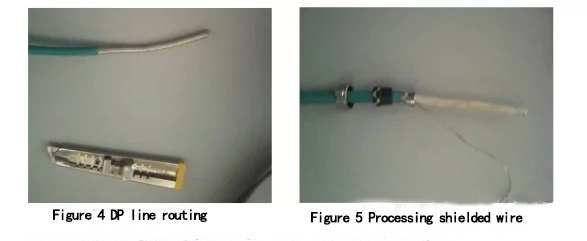
c) The inner metal shielding layer is repeatedly opened, and twisted into a strand, as shown in Figure 5;
d) Strip off the white protective layer inside the cable, connect the shielding layer to the screw marked by the oval in Figure 7, and connect the network cable, A to the green wire, B to the red wire, as shown in Figure 6, Figure 7.
Advantages and disadvantages of this method:
Advantages: good shielding layer contact;
Disadvantages: the wiring method is complicated and not easy to operate
Encoder wiring method 2:
Tools needed: DP wire stripping knife, 2mm slotted screwdriver, a set of six flowers, a pair of pliers, and a Phillips screwdriver with 3mm opening. Steps:
3) Wiring:
a) Strip the wire with a professional DP wire stripper, put on the accessories in order according to Figure 8, and shield;
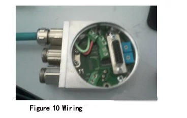
b)Wiring, connect A to the green wire and B to the red wire, as shown in Figure 10.
Advantages and disadvantages of this method:
Advantages: simple wiring method, easy to operate;
Disadvantages: The shielding layer is prone to poor contact.
5-wire encoder wiring method:
1. The program uses a one-way counter to connect to a DC24V power supply and an A;
2. If you are using a two-way counter to connect to the DC24V power supply and A, B can be. It should be noted that A and B need to be connected to the input point of the PLC with high-speed counting function;
3. The three cores are connected to +, -, and A phases, according to the encoder manual.
The 5 wires are A/B/Z, plus two power wires; the 5 wires are incremental wire-saving encoder cables, including quadrature encoding, motor zero and power wires for common ground transmission, and sector Huo Er signal is shared with ABZ, it is occupied by UVW for a short time when power is on; 5 programs are processed slightly, the encoder power supply must be controlled when starting, and the number of cable cores is less than that of multi-wire type.
-
The principle and application field of Autonics panel products (handling)
 June 12, 2021
 -
New product launch SRH1 series single-phase SSR with integrated heat sink
 June 12, 2021
 -
New product launch SRH1 series single-phase SSR with integrated heat sink
 June 12, 2021
 -
Otto protection grade IP69K new product launched Ø18mm cylindrical (SUS316L housing) photoelectric sensor BRQT series
 June 12, 2021
 -
Autonics adds shading motion mode sensor
 June 12, 2021