[Experience] How to understand the real encoder and decoder
[Experience] How to understand the real encoder and decoder
Before entering the reality of encoders and decoders, let us briefly think about multiplexing. Usually we will need to load some input signals one at a time into a separate load application. The process of selecting one of the input signals is called multiplexing. The reversal of this operation, that is, to nourish a small amount of load from a common signal source is called demultiplexing. Similarly, in the digital domain, for the simplicity of information transmission, information is periodically scrambled or set in a code, and after that, the security code is transmitted. At the collector, the encoded information is decoded or accumulated from the code, and processed to be also displayed or given a load.
The encoder and decoder complete the distribution of information encryption and decryption information. So how do we understand the real encoder and decoder now?
What is a decoder?
The decoder is a multiple-input multiple-output logic circuit, which turns the code i/ps into coded o/ps, where the input and output are not similar, such as n-2n, and a binary coded decimal decoder. Decoding is essential in applications such as data multiplexing, memory address decoding and 7-segment display. The best example of a decoder circuit is an AND gate, because when all inputs are "high", the output of this gate is "high", which is the so-called "high-level effective output". As an alternative to the AND gate, the NAND gate is connected, and only when all its inputs are "high", the output will be "low" (0). Such o/p is called "active low output".
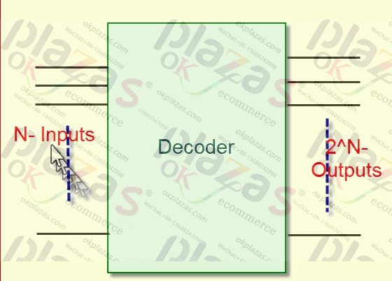
A slightly more difficult decoder would be a binary decoder of type n to 2n. These types of decoders are combinational circuits that can modify binary information from n-encoded input to mostly 2n-exclusive output. If the subsequent bit-encoded data has free bit combinations, the decoder may have less than 2n outputs. Other examples include 2 to 4, 3 to 8 line decoders or 4 to 16 decoders.
Parallel binary number is the input of the decoder, used to pay attention to the specific binary number appearing at the input. The output shows the presence or absence of precise numbers at the decoder input.
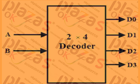
2 to 4 wire decoder circuit design
Similar to the multiplexer circuit, the decoder is not limited to a specific address line, so it can have more than two outputs (with two, three or four address lines). The decoder circuit can decode 2, 3 or 4 binary numbers, or can decode up to 4, 8 or 16 time-division multiplexed signals.
As a decoder, the circuit uses an n-bit binary number and produces an output on one of the output lines. Therefore, it is usually described by the number of addressing i/p lines and the number of data o/p lines. A typical decoder IC may include two 2-4 line circuits, a 3-8 line circuit or a 4-16 line decoder circuit. One exclusion of the binary characters of this circuit is the 4-10 line decoder, which is proposed to change the binary coded decimal (BCD) input to an output in the 0-9 range.
If you use this circuit as a decoder, you may need to insert a data latch at o/ps to keep each signal while transmitting other signals. However, when you use this circuit as a decoder, it is not relevant to you, so you only need a valid o/p to equal the input code.
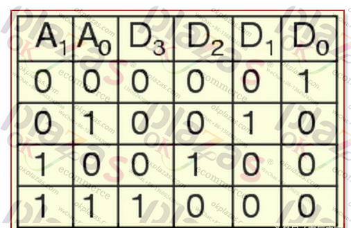
2 to 4 line decoder truth table
In this type of decoder, the decoder has two inputs, namely A0, A1 and four outputs represented by D0, D1, D2, and D3. As you can see in the truth table below-for each input combination, open an o/p line.
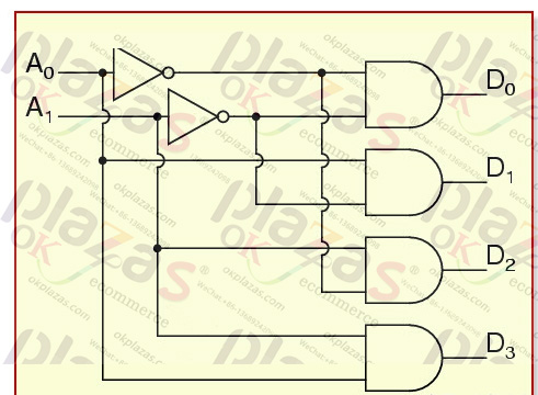
In the above example, you can observe that the o/p of each decoder is indeed a minimum term, which is generated by a certain input combination, namely:
D0=A1A0, (mintermm0) corresponds to input terminal 00D1=A1A0, (mintermm1) corresponds to input terminal 01D2=A1A0, (mintermm2) corresponds to input terminal 10D3=A1A0, (mintermm3) corresponds to input 11 as shown in the figure, the circuit Use AND gate to achieve. In this circuit, the logic equation of D0 is A1/A0, and so on. Therefore, each output of the decoder will be generated as an input combination.
-
The principle and application field of Autonics panel products (handling)
 June 12, 2021
 -
New product launch SRH1 series single-phase SSR with integrated heat sink
 June 12, 2021
 -
New product launch SRH1 series single-phase SSR with integrated heat sink
 June 12, 2021
 -
Otto protection grade IP69K new product launched Ø18mm cylindrical (SUS316L housing) photoelectric sensor BRQT series
 June 12, 2021
 -
Autonics adds shading motion mode sensor
 June 12, 2021