How do you look at the voltmeter measurement object And give an example
How do you look at the voltmeter measurement object And give an example
How do you look at the voltmeter measurement object And give an example
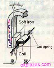
A voltmeter is an instrument for measuring voltage, and the symbol of a commonly used voltmeter-voltmeter is "V". The traditional analog voltmeter includes a sensitive ammeter. There is a permanent magnet in the sensitive ammeter. A coil composed of a wire is connected in series between the two terminals of the ammeter. The coil is placed in the magnetic field of the permanent magnet. It is connected with the pointer of the watch through the transmission device. Most voltmeters are divided into two ranges. The voltmeter has three terminals, one negative terminal, and two positive terminals. The positive terminal of the voltmeter is connected to the positive terminal of the circuit, and the negative terminal is connected to the negative terminal of the circuit.
Traditional analog voltmeters and ammeters are based on a principle that is the magnetic effect of current. The greater the current, the greater the magnetic force produced, which shows the greater the swing of the pointer on the voltmeter. There is a magnet and a wire coil in the voltmeter. After passing the current, the coil will generate a magnetic field. After the coil is energized The deflection occurs under the action of the magnet, which is the head part of the ammeter and voltmeter.
Since the voltmeter needs to be connected in parallel with the measured resistance, if the sensitive ammeter is directly used as a voltmeter, the current in the meter will be too large and the meter will be burnt out. At this time, a large resistance needs to be connected in series with the internal circuit of the voltmeter. After this transformation, when the voltmeter is connected in parallel again in the circuit, most of the voltage applied to the two ends of the meter is shared by the series resistance due to the effect of the resistance, so the current through the meter is actually very small, so It can be used normally. The symbol of DC voltmeter should add a "_" under V, and the symbol of AC voltmeter should add a wavy line "~" under V.
How do you see the voltmeter measurement object?
1. Short circuit method
Remove the voltmeter and assume that the wire is connected to this position. If some electrical appliances or power sources are short-circuited at this time, these electrical appliances or power sources are the objects measured by the voltmeter.
2. De-source method
"Remove" the power supply (cover the power supply with your hand), and then look at which part of the voltmeter forms a closed loop, then the voltmeter measures the voltage of that part of the circuit.
3. Sliding line method
The two ends of the voltmeter slide along the connected wires to the ends of the electrical appliance or power source. (Able to cross components: switches, ammeters. Cannot cross components: power supplies, electrical appliances, voltmeters.)
Special Instructions:
1. Connecting the voltmeter to the circuit is equivalent to an open circuit there.
2. The ammeter connected to the circuit is equivalent to a wire.
3. The voltmeter and the electrical appliance are connected in series and connected to both ends of the power supply. The voltmeter measures the power supply voltage.
Examples of voltmeter measurement objects:
In a series circuit, the following ideas and methods can be used to quickly and accurately determine which part of the circuit voltage is measured by the voltmeter:
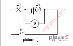
Example 1: The circuit shown in Figure 1: The voltage of the power supply is 6V. After the switch S is closed, the voltage measured by the voltmeter is ()
A.The voltage across L1
B, the voltage across L2
C, the total voltage across L1 and L2
D, the voltage across the power supply
Analysis:
Method 1: Regard the voltmeter as a "branch" of the circuit, find the two points connected by the voltmeter and use them as nodes. In addition to the voltmeter, the original circuit is divided into two parts, both of which are regarded as being connected in parallel with the voltmeter. In the circuit, there is a light bulb L2 in series with the power supply, and the other part only contains L1. The voltmeter measures the voltage across the part of the circuit without the power supply, that is, the voltage across L1.
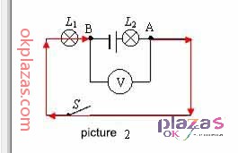
Method 2: As shown in the figure below, find the two points connected by the voltmeter, start from a point close to the positive pole of the power supply (point A), and follow the direction of current flow to another point close to the negative pole of the power supply (point B). If there is L1 on some lines, measure the voltage across L1.
Example 2: The circuit shown in the figure below, the connection of bulbs L1 and L2 is connected, the voltmeter V1 measures voltage, and the voltmeter V2 measures voltage.
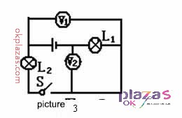
Analysis: When judging the circuit, regard the voltmeter as an open circuit and remove it directly from the circuit. It can be seen that the bulbs L1 and L2 are connected in series. The voltmeter V1 is connected in parallel with the bulb L2. The voltage across L2 is measured. The voltmeter V2 is connected in parallel with the bulb L1. Measure the voltage across L1.
-
The principle and application field of Autonics panel products (handling)
 June 12, 2021
 -
New product launch SRH1 series single-phase SSR with integrated heat sink
 June 12, 2021
 -
New product launch SRH1 series single-phase SSR with integrated heat sink
 June 12, 2021
 -
Otto protection grade IP69K new product launched Ø18mm cylindrical (SUS316L housing) photoelectric sensor BRQT series
 June 12, 2021
 -
Autonics adds shading motion mode sensor
 June 12, 2021