How to realize the positioning function of encoder with PLC control
How to realize the positioning function of encoder with PLC control
How to realize the positioning function of encoder with PLC control
Strictly speaking, the encoder will only tell you how to position and how to execute it. It is necessary to rely on the CNC system (or PLC and other controllers) to control the servo or stepper motor to achieve positioning. The encoder is like human eyes, knowing The motor shaft or load is at a certain current position. Generally, photoelectric type encoders are used in industry. A brief explanation is given below.
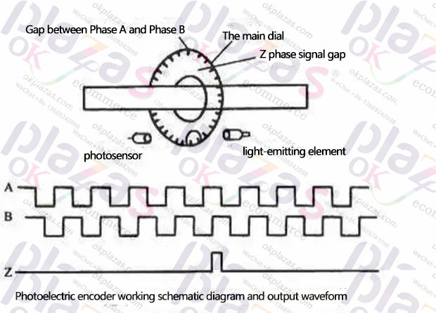
Strictly speaking, the encoder will only tell you how to position and how to execute it. It is necessary to rely on the CNC system (or PLC and other controllers) to control the servo or stepper motor to achieve positioning. The encoder is like human eyes, knowing The motor shaft or load is at a certain current position. Generally, photoelectric type encoders are used in industry. A brief explanation is given below.
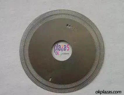
Then there is a precise luminous source, installed on one side of the code wheel, and on the other side of the code wheel, there will be a receiver or the like, using photoresistors, these components plus amplification and shaping circuits, so that when the code wheel rotates, there is The light will pass through the gap, and the receiver will instantly receive the light pulse. After the circuit is processed, it will output an electrical pulse signal. In this way, the code wheel will rotate for a circle and will output 1024 pulses. If the first pulse position is 0 , The second pulse position is 0.3515625°, the third pulse position is 0.3515625°*2, and so on, so as long as there is an instrument that can read the number of pulses, you can know where the code disc corresponds. If you encode The encoder is installed on the shaft of the motor. The motor shaft and the encoder are rigidly connected, and the positional relationship between the two will correspond one to one. By reading the encoder pulse, the shaft position of the motor can be known.
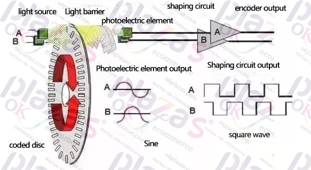
The motor shaft, for example, will drive some loads through timing belts, gears, chains, etc., such as controlling the screw rod, so there will be a so-called electronic gear ratio relationship, the motor rotates, how many millimeters will the screw rod advance, so read the corresponding The number of pulses output from the encoder can be used to infer the current position of the screw.
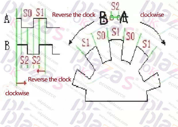
But the encoder is round. If it rotates indefinitely, the angle will be infinite. Therefore, an incremental encoder is designed. One rotation will output three sets of signals ABZ, where AB is the same pulse. There are 1024 pulses in one circle, AB phase pulse corresponds to the circle angle in one circle, and the two pulses are in orthogonal state. If it is forward and reverse, by judging the sequence of the rising edge and falling edge of the AB phase pulse, You can know whether the encoder is currently rotating clockwise or counterclockwise.
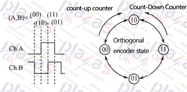
In addition, there is a Z-phase pulse, because although the circle will continue to rotate, the angle will be endless, but it is only a cycle of repetition, the zero-phase pulse is fixed at a certain position on the circle, and the encoder only outputs every time it rotates. A zero-phase pulse, so if the Z-phase pulse is used as the reference point, the system will be cleared every time the pulse is read, and the maximum angle can be controlled within 360°, which is equivalent to a zero reference point .
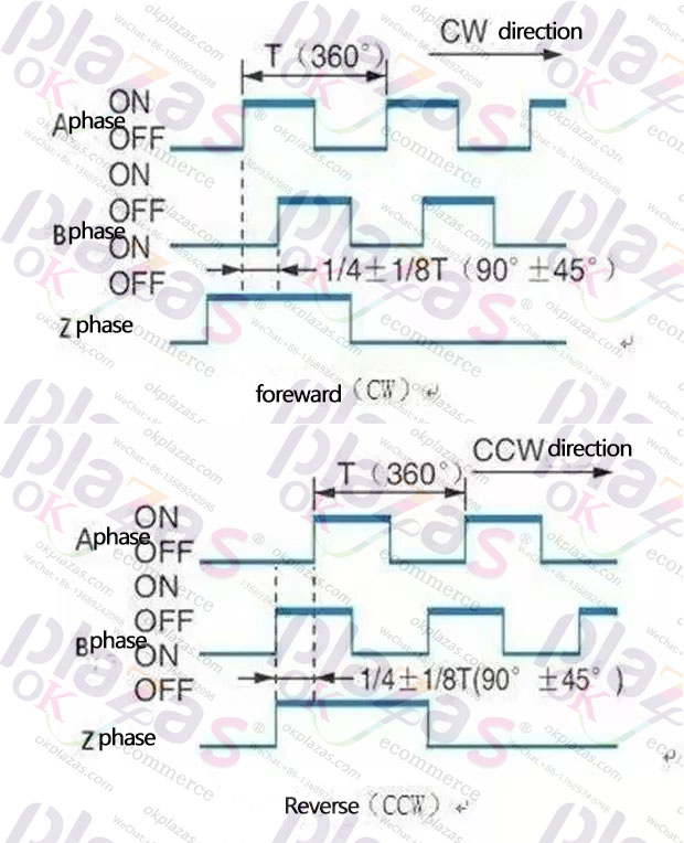
In this way, even if the system is disconnected and powered on again, as long as the reference point can be found, the initial position of the screw can be known.
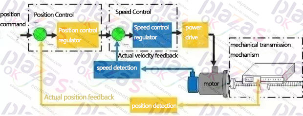
The above positioning is called an incremental coordinate system, so the encoder is an incremental encoder, which is widely used because it is flexible and cheap.
If the device only needs to make one revolution, that is, the angle is within 360°, the encoder can be subdivided into a bit more precise, for example, there are 13 bits, which is equivalent to 2^13 pulses per revolution, which corresponds to 360°. There is a one-to-one correspondence between the number of pulses and the angle, and you are not afraid that the system needs to re-adjust the zero position when the system is powered off. This kind of encoder is called a single-turn absolute encoder. If the load needs to rotate multiple times, but the number of turns can not be very large, such as 5 turns, which is equivalent to 5*360°=1800°, so the pulse corresponds to 1800° one-to-one. These are compared in some high-end CNC machine tools. Many, you can know the current precise position of the screw or some rotating work, and there is no need to worry about the system power failure and resetting.
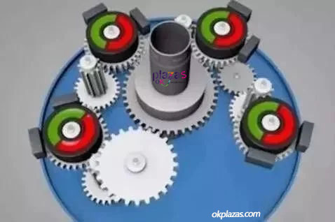
In addition, the encoder also has a magnetoelectric method. For example, a large number of small magnets spaced from north to south are processed on the code disc. The signal of the small magnet is read through the Hall, and the output signal is also amplified and shaped into electric pulses. The dot and the photoelectric encoder are similar, and the price will be cheaper, the reliability will be higher, but the accuracy is worse than the photoelectric encoder.
02
How does PLC judge position through encoder
PLC can input switch quantity, that is, a high and one low level voltage, and the encoder pulse signal can understand a group of switch quantities completed in a certain period of time with extremely fast speed. But because the frequency of this switch is too high, the ordinary I/O port of the PLC cannot accurately read the number of these pulses, because there is a scan cycle in the PLC working process, and it needs to be refreshed every period of time. The data of the ordinary I/O port, and the accuracy of the encoder is too high, the number of pulses output per unit time is too much, ordinary I/O is not competent
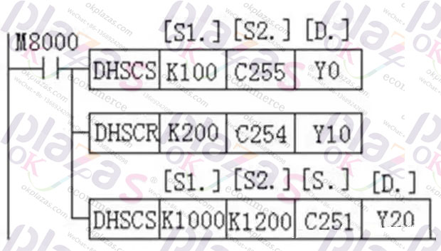
Generally, PLCs are designed with high-speed counting ports. The essence is to use the hardware logic of the underlying single-chip microcomputer to complete the counting of these encoders, avoiding the scan cycle problem, and PLCs are designed with special high-speed counting instructions. When using them, directly call these The instruction can read the current pulse value.
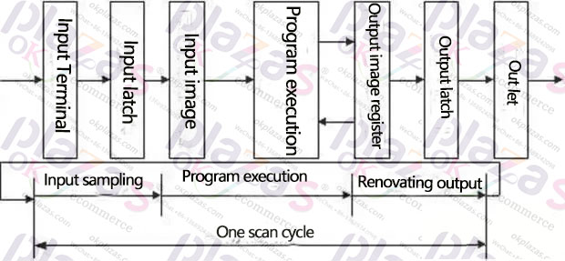
However, in the calculation and output of the pulse, due to the existence of the scan cycle, there will often be a hysteresis effect. If it is used to control some actuators, such as a cylinder to actuate the cutting action, then the compensation of the advance must be considered.
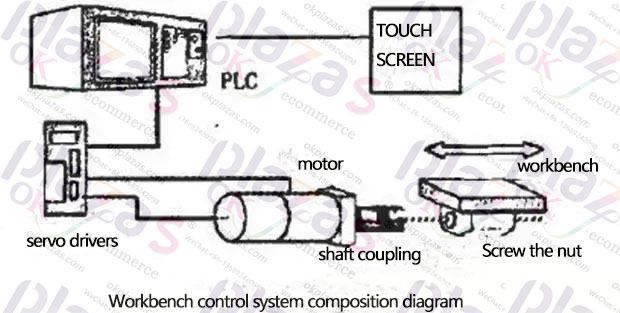
As a reminder, if you want to use a PLC to control a servo or stepping system, you often don’t need to use encoder feedback to judge the position, and send position pulses to the servo drive through some PLS instructions. The position loop is built inside the servo drive. Well, the PLC here is just a command mechanism and does not constitute a position closed loop. Of course, if it is controlled by a dedicated positioning module, using a control method such as NC, a position closed loop can be built inside.


