In-depth analysis | Why should the inverter be connected to a braking resistor?
In-depth analysis | Why should the inverter be connected to a braking resistor?
In-depth analysis | Why should the inverter be connected to a braking resistor?
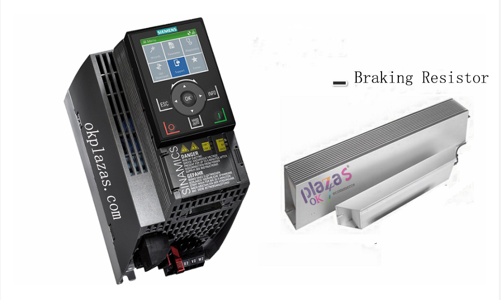
In the motor drive system using AC frequency converters, some frequency converters are connected to the outside of the braking resistor, and some frequency converters seem to be disconnected. So the question is, what is the braking resistor used for? Why connect a braking resistor? In today's article, we will talk about the braking resistor of the inverter.
To explain clearly how the braking resistor works, we have to start with the working principle of the motor.
We know that the speed formula of a three-phase asynchronous motor is: n=60f/p(1-s). “N” represents the speed of the motor; “f” represents the frequency of the AC power supply; “p” represents the number of pole pairs of the motor; “s” represents the slip rate (the difference between the speed n0 of the synchronous magnetic field and the speed n of the asynchronous motor And the ratio of the rotation speed n0 of the synchronous magnetic field). For a finished motor, the number of pole pairs p is constant, so we can only change the speed of the asynchronous motor by changing the frequency of the AC power supply. This is also the theoretical basis for the speed regulation of the AC inverter.
Three-phase asynchronous motors have two operating states-electric operating state and generating operating state.
1. Electric running state:
When the three-phase asynchronous motor is connected to the power supply, it will produce a rotating magnetic field (this magnetic field is synchronized with the magnetic field of the three-phase alternating current, so it is also called a synchronous magnetic field). The rotating magnetic field cuts the rotor windings to generate induced electromotive force, thereby generating current in the rotor windings. The rotor windings that generate current are subjected to electromagnetic force in the rotating magnetic field to generate electromagnetic torque, so the three-phase asynchronous motor rotates. In this case, the speed n of the asynchronous motor is always less than the speed n0 of the rotating magnetic field. At this time, the magnetic field drives the motor to run, and the motor is in an electric state. In the electric state, the direction of the electromagnetic torque is the same as that of the motor.
2. Power generation operation status:
In the electric state, the rotation speed n of the motor continues to increase through external force. At a certain moment when n is greater than the speed n0 of the rotating magnetic field, the direction of the electromotive force generated by the rotor windings will be reversed, and the current in the rotor will flow in the reverse direction, thus generating an electromagnetic torque opposite to the direction of the motor. In this case, the electromagnetic torque plays a role of braking, and the asynchronous motor is in a generating operation state. Typical scenarios in the power generation state are cranes quickly lowering heavy objects, electric vehicles rapidly descending slopes, and rapid parking.
In AC frequency conversion speed regulation, the frequency converter achieves the purpose of changing the motor speed by changing the frequency of the output power supply (change the voltage while frequency conversion). Increase the frequency to accelerate the motor, and decrease the frequency to decelerate the motor.
In a drag system with large load inertia, the inverter reduces the frequency to slow down the motor and stop. At the moment the frequency decreases, the speed of the synchronous magnetic field of the motor also decreases. However, due to mechanical inertia, the speed of the rotor does not decrease instantaneously. At this time, the motor speed n is greater than the speed of the synchronous rotating magnetic field, and the motor is in a power generation operation state. The electromagnetic torque becomes the braking torque to promote the reduction of the motor speed, and the regenerated electric energy returns to the DC bus after rectification. In a frequency converter without an energy feedback unit, the regenerative energy cannot be fed back to the grid and can only be absorbed by the capacitor of the frequency converter. This will cause the voltage of the capacitor to rise rapidly in a short time, which is called "pumping voltage". The pumping voltage causes the DC voltage to rise sharply, which may break down components and damage the inverter.
In order to solve the problem of pumping voltage, a braking resistor is used in a frequency converter without an energy feedback unit to consume regenerative power. When the voltage of the DC bus rises to the threshold, the braking unit will open the channel of the braking resistor, and the regenerative electric energy will be consumed in the braking resistor in the form of heat. Braking resistors have different powers and should be selected according to actual conditions. Many inverters have a small braking resistor connected internally, but if there is a lot of regenerative energy, an external braking resistor is also required.
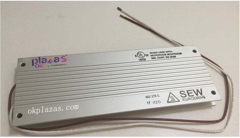
The picture below is the appearance of the braking resistor of SEW inverter:
Another way to solve the pumping voltage is to integrate an energy feedback unit in the frequency converter. In a frequency converter with an energy feedback unit, the regenerative electric energy is fed back to the grid through the energy feedback unit, which really achieves the purpose of energy saving. However, inverters with integrated energy feedback units are usually more expensive, and based on cost considerations, there are still relatively few equipment using such inverters.
I believe that after reading this, you should be very clear why the inverter needs to be connected to a braking resistor. Those that cannot be seen from the outside, in fact, have a small braking resistor integrated inside.
Well, the introduction of the braking resistor of the frequency converter is here.
-
The principle and application field of Autonics panel products (handling)
 June 12, 2021
 -
New product launch SRH1 series single-phase SSR with integrated heat sink
 June 12, 2021
 -
New product launch SRH1 series single-phase SSR with integrated heat sink
 June 12, 2021
 -
Otto protection grade IP69K new product launched Ø18mm cylindrical (SUS316L housing) photoelectric sensor BRQT series
 June 12, 2021
 -
Autonics adds shading motion mode sensor
 June 12, 2021