Incremental rotary encoder working principle and installation steps
Incremental rotary encoder working principle and installation steps
Incremental rotary encoder working principle and installation steps
Working principle of incremental rotary encoder
Incremental rotary encoders do not have a fixed starting zero point, and output pulses that are proportional to the increase in the angle of rotation. A counter is needed to count the pulses. Each time a light-transmitting area is rotated, a pulse signal is sent out, and then the pulse signal is counted by the high-speed counter of the PLC to obtain the measurement result.
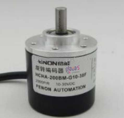
Wiring method of incremental rotary encoder
Incremental rotary encoders generally have 5 leads, one is the COM terminal line, the other is the power line, and the remaining three are pulse output lines. First, the power-terminal should be connected to the COM terminal of the encoder, and then the + terminal should be connected to the power terminal of the encoder. At this time, the COM terminal of the encoder is connected with the PLC input COM terminal, and the A, B, Z two-phase pulse output lines are directly connected with the input terminal of the PLC. A and B are pulses with a difference of 90 degrees. Finally, the incremental rotary encoder has a shielded wire. Grounding the shielded wire when in use can effectively improve the anti-interference ability.
Points to note: When the working voltage is different from the PLC input voltage, one thing to note is that the external power supply voltage must be below DC30V. If the working voltage is exceeded, the encoder may be damaged.
Installation steps of incremental rotary encoder
1. Install the encoder firmly to avoid loosening due to vibration during use.
2. When wiring the encoder, please confirm that the load cannot exceed its maximum allowable value and deviation.
3. Tighten the screws around the encoder coupling to avoid loosening during use.
Four points should be paid attention to when using incremental rotary encoder
1. Vibration applied to the rotary encoder will often cause false pulses. Therefore, attention should be paid to the installation location and installation location. When the number of pulses generated per revolution is greater, the gap between the slots of the rotating grooved disk is narrower, and the more susceptible to vibration is. When rotating or stopping at a low speed, the vibration added to the shaft or body of the encoder makes the rotary grooved disc jitter, and false pulses may occur at any time.
2. Wiring should be done when the power is off. When the power is turned on, if the output wire contacts the power supply, the encoder output circuit may be damaged.
3. Pay attention to the polarity of the power supply when wiring the encoder. If the wiring is wrong, the internal circuit of the encoder may be damaged.
4. In order to avoid encoder induced noise, etc., try to use the shortest wiring. When inputting to an integrated circuit, this is especially important.
-
The principle and application field of Autonics panel products (handling)
 June 12, 2021
 -
New product launch SRH1 series single-phase SSR with integrated heat sink
 June 12, 2021
 -
New product launch SRH1 series single-phase SSR with integrated heat sink
 June 12, 2021
 -
Otto protection grade IP69K new product launched Ø18mm cylindrical (SUS316L housing) photoelectric sensor BRQT series
 June 12, 2021
 -
Autonics adds shading motion mode sensor
 June 12, 2021