Installation method of Yaskawa encoder and common alarm codes of driver
Installation method of Yaskawa encoder and common alarm codes of driver
Installation method of Yaskawa encoder and common alarm codes of driver
1. Remove the three screws at 1, 2, and 3
二. Screw in with an M6 screw
(2) Push out the encoder at the middle screw hole
(can't pry out)
三. When the encoder and the steel sheet are installed,
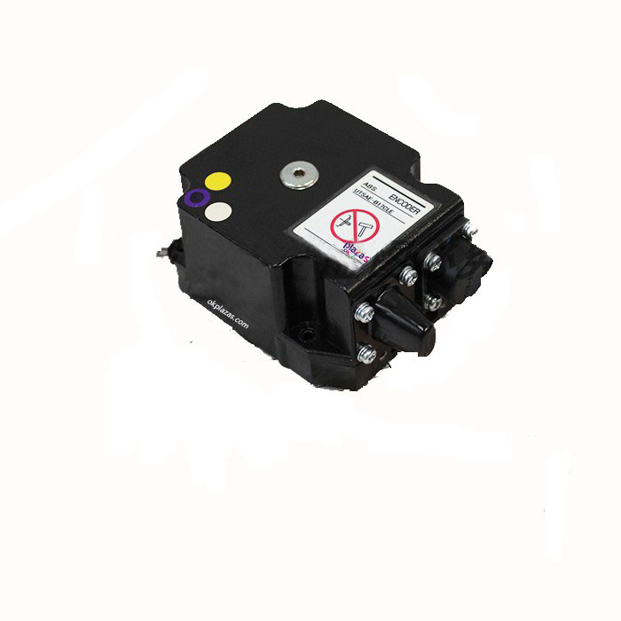
Encoder yellow jack (1)
and the small gap of the steel sheet (2) need to be in the opposite direction
4. The bayonet of the encoder must be aligned with the bayonet of the motor during installation
Note that the direction of the yellow socket of the encoder is on the left hand side after installation
(viewed from behind the motor)
Other encoder installation related content
■Mechanical aspects
Real shaft type: Do not rigidly connect the encoder shaft and the user shaft, please use an elastic coupling.
When installing, please pay attention to the allowable shaft load of the encoder.
Empty shaft type: Do not rigidly connect the encoder shaft and the user shaft, please use an elastic coupling plate.
When installing, please pay attention to the allowable shaft load of the encoder.
■Electrical aspects
Please do not wind the encoder output line and power line together or transmit in the same pipeline, nor should it be used near the switchboard. When wiring, please press
Wiring table or instruction manual, turn on after checking
Common alarm codes of Yaskawa servo drives
Yaskawa Drive and Motor
1, A.00 absolute value data error:
Absolute value data cannot be accepted or the received absolute value data is abnormal.
2, A.02 parameter destruction:
The result of "sum check" of user constant is abnormal.
3, A.04 User constant setting error:
The set "User Constant" exceeds the setting range.
4, A.10 Excessive current:
The power transistor current is too large.
5, A.30 Regeneration abnormality detected:
The regeneration processing circuit is abnormal.
6, A.31 Position deviation pulse overflow:
The position deviation pulse exceeds the value of the user constant "Overflow (Cn-1E)".
7, A.40 The main circuit voltage is abnormal:
The main circuit is abnormal.
8, A.51 speed is too high:
The rotation speed of the motor exceeds the detection level.
9, A.71 Super high load:
Running for a few seconds to tens of seconds is greatly exceeded the rated torque.
10, A.72 Ultra-low load:
Continuous operation exceeds the rated torque.
11, A.80 Absolute encoder error:
The number of pulses per revolution of the absolute encoder is abnormal.
12, A.81 Absolute encoder backup error:
The three power supplies (+5v, the internal capacitor of the battery pack) of the absolute encoder are all dead.
13, A.82 Absolute encoder sum check error:
The result of "sum check" in the memory of the absolute encoder is abnormal.
14, A.83 Absolute encoder battery pack error:
The battery pack voltage of the absolute encoder is abnormal.
2020/12/15 YASKAWA encoder UTSAE-B17CLE_Encoder_Enterprise Blog
http://www.bokee.net/company/weblog_viewEntry/35618062.html 3/5
15, A.84 Absolute encoder data error:
The received absolute value data is abnormal.
16, A.85 Absolute encoder overspeed:
When the absolute value encoder is powered on, the speed can reach more than 400r/min.
17, A.A1 heat sink is overheated:
The radiator of the servo unit is overheated.
18, A.B1 command input and reading error:
The CPU of the servo unit cannot detect command input.
19, A.C1 servo out of control:
The servo motor (encoder) is out of control.
20, A.C2 measured the phase difference of the encoder:
The phase of the ABC three-phase output of the encoder is abnormal.
21, A.C3 Encoder A-phase and B-phase disconnection:
The A-phase and B-phase of the encoder are disconnected.
22, A.C4 Encoder C phase disconnection:
The encoder phase C is disconnected.
23, A.F1 power cord lack phase:
One phase of the main power supply is not connected.
24, A.F3 momentary power failure error:
In alternating current, there is a power outage that exceeds one power cycle.
25, CPF00 digital operator communication error-1:
After 5 seconds of power on, it still cannot communicate with the servo unit.
26, CPF01 digital operator communication error-2:
The data communication is bad for 5 consecutive times.
27, A.99 no error display:
shows the normal operating state.
-
The principle and application field of Autonics panel products (handling)
 June 12, 2021
 -
New product launch SRH1 series single-phase SSR with integrated heat sink
 June 12, 2021
 -
New product launch SRH1 series single-phase SSR with integrated heat sink
 June 12, 2021
 -
Otto protection grade IP69K new product launched Ø18mm cylindrical (SUS316L housing) photoelectric sensor BRQT series
 June 12, 2021
 -
Autonics adds shading motion mode sensor
 June 12, 2021