Pepperl+Fuchs encoder wiring analysis okplazas.com to share with you
Pepperl+Fuchs encoder wiring analysis okplazas.com to share with you
Pepperl+Fuchs encoder wiring analysis okplazas.com to share with you
Dear P+F Pepperl+Fuchs encoder enthusiasts, in view of the fact that some "compilers" are very concerned about the use of encoders. The editor of okplazas.com is here to share with you the wiring method of the rotary encoder. Let's take an example. For example: connect to PLC, take CPM1A as an example, the brown wire of the encoder is connected to the positive electrode of the encoder working voltage, the blue wire is connected to the negative electrode of the encoder working voltage, the output wire is connected to the input point of the PLC in turn, the blue wire is connected to the negative electrode of the external power supply, and the external power supply The positive terminal is connected to the input com terminal of the PLC.
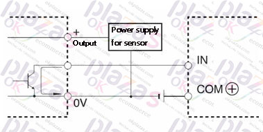
As shown in FIG. A safe method can also be selected: Method 2: Connect the brown wire of the encoder to the positive pole of the power supply, connect the output wire to the input point of the PLC in turn, connect the blue wire to the negative pole of the power supply, and then pull a wire from the positive end of the power supply to the PLC input com terminal. The brown wire of the encoder is connected to the positive pole of the power supply, the output wire is connected to the input point of the PLC in turn, the blue wire is connected to the negative pole of the power supply, and then a wire is drawn from the positive end of the power supply to the PLC input com terminal. The specific wiring method is as follows: the brown wire is connected to the positive pole of the power supply, the blue wire is connected to the negative pole of the power supply, and then a wire is drawn from the negative end of the power supply to terminal 6; the black and white wires are connected to terminals 8 and 9, if automatic reset is required, orange The line is connected to the No. 7 terminal. Look at the output. The wiring of P+F Pepperl+Fuchs encoder has two groups of A. B. Z. Now there are 6 wires, +V, 0V and then FG. What should your encoder be connected to? Is it connected to a PLC, a motor, or a counter? Generally, the wiring is VCC connected to the power supply, line A is input A, item B is connected to the common terminal, item Z is a weekly pulse item, one pulse per week . If it is counting, you can leave out the Z item.
-
The principle and application field of Autonics panel products (handling)
 June 12, 2021
 -
New product launch SRH1 series single-phase SSR with integrated heat sink
 June 12, 2021
 -
New product launch SRH1 series single-phase SSR with integrated heat sink
 June 12, 2021
 -
Otto protection grade IP69K new product launched Ø18mm cylindrical (SUS316L housing) photoelectric sensor BRQT series
 June 12, 2021
 -
Autonics adds shading motion mode sensor
 June 12, 2021