Principle and application circuit of photoelectric encoder
Principle and application circuit of photoelectric encoder
Principle and application circuit of photoelectric encoder
1.Principle of photoelectric encoder
According to the detection principle, encoders can be divided into optical, magnetic, inductive and capacitive. According to its scale method and signal output form, it can be divided into three types: incremental, absolute and hybrid.
1.1 Incremental encoder
Incremental encoders directly use the principle of photoelectric conversion to output three sets of square wave pulses A, B, and Z; the phase difference of the two sets of pulses is 90 per revolution. The phase difference of the two sets of pulses is 90. Pulse, used for reference point positioning. Its advantages are simple structure, average mechanical life of more than tens of thousands of hours, strong anti-interference ability, high reliability, and suitable for long-distance transmission. The disadvantage is that the absolute position information of the shaft rotation cannot be output.
1.2 Absolute encoder
The absolute encoder is a sensor that directly outputs digital quantities. There are several concentric code tracks along the radial direction on its circular code disc. Each track is composed of light-transmissive and opaque sectors. The fans of adjacent code channels The number of zones is a double relationship. The number of code channels on the code wheel is the number of binary digits. On one side of the code wheel is the light source, and the other side has a photosensitive element corresponding to each code channel; when the code wheel is in different positions When, each photosensitive element converts a corresponding level signal according to whether it receives light or not, and forms a binary number. The characteristic of this kind of encoder is that no counter is needed, and a fixed digital code corresponding to the position can be read out at any position of the shaft. Obviously, the more code channels, the higher the resolution. For an encoder with N-bit binary resolution, the code disk must have N code channels. At present, there are 16-bit absolute encoder products in China.
The absolute encoder uses natural binary or cyclic binary (Grey code) method for photoelectric conversion. The difference between an absolute encoder and an incremental encoder is the transparent and opaque line pattern on the disc. The absolute encoder can have several codes, and the absolute position can be detected according to the code on the read code disc. The coding design can adopt binary code, cyclic code, two's complement code, etc. Its unique features are:
1.2.1 The absolute value of angle coordinates can be read directly;
1.2.2 There is no cumulative error;
1.2.3 The position information will not be lost after the power is cut off. But the resolution is determined by the number of bits in the binary system, which means that the accuracy depends on the number of bits. There are currently 10 bits, 14 bits, and so on.
1.3 Hybrid absolute encoder
Hybrid absolute encoder, it outputs two sets of information: one set of information is used to detect the magnetic pole position, with absolute information function; the other set is exactly the same as the output information of the incremental encoder.
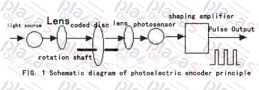
The photoelectric encoder is an angle (angular velocity) detection device. It converts the angle input to the shaft into the corresponding electric pulse or digital quantity by using the photoelectric conversion principle. It has the advantages of small size, high precision, reliable work, and digital interface. . It is widely used in devices and equipment that need to detect angles such as CNC machine tools, rotary tables, servo drives, robots, radars, and military target determination.
2. Application circuit of photoelectric encoder
2.1 Application of EPC-755A photoelectric encoder
EPC-755A photoelectric encoder has good performance, strong anti-interference ability in angle measurement and displacement measurement, and has a stable and reliable output pulse signal, and the measured digital signal can be obtained after the pulse signal is counted. Therefore, when we are developing a car driving simulator, we use the EPC-755A photoelectric encoder as the sensor for the measurement of the steering wheel rotation angle, the output circuit of which is an open collector type, and the output resolution is 360 pulses/turn. Taking into account the car steering wheel The rotation is bidirectional, it can rotate clockwise or counterclockwise, and the output signal of the encoder can be counted after phase discrimination. Figure 2 shows the actual phase detection and two-way counting circuit of the photoelectric encoder. The phase detection circuit is composed of 1 D flip-flop and 2 NAND gates, and the counting circuit is composed of 3 pieces of 74LS193.
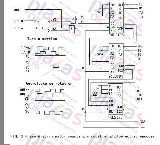
When the photoelectric encoder rotates clockwise, the output waveform of channel A leads the output waveform of channel B by 90°, the output of D trigger Q (waveform W1) is high level, Q (waveform W2) is low level, and the upper NAND gate is opened , The counting pulse passes (waveform W3), and is sent to the plus pulse input terminal CU of the bidirectional counter 74LS193 for counting up; at this time, the following NAND gate is closed and its output is high (waveform W4). When the photoelectric encoder rotates counterclockwise, the output waveform of channel A is delayed by 90° from the output waveform of channel B, the output of D flip-flop Q (waveform W1) is low level, Q (waveform W2) is high level, and the above NAND gate Closed, its output is high level (waveform W3); at this time, the lower NAND gate is opened, the counting pulse passes (waveform W4), and is sent to the decrement pulse input CD of the bidirectional counter 74LS193 for decrement counting.
When the car steering wheel rotates clockwise and counterclockwise, its maximum rotation angle is two and a half turns. An encoder with a resolution of 360 pulses/turn is selected, and its maximum output pulse number is 900; the actual counting circuit uses 3 pieces 74LS193 composition, when the system is powered on and initialized, first reset it (CLR signal), and then set its initial value to 800H, which is 2048 (LD signal); in this way, when the steering wheel rotates clockwise, the output range of the counting circuit It is 2048~2948. When the steering wheel rotates counterclockwise, the output range of the counting circuit is 2048~1148; the data output D0~D11 of the counting circuit are sent to the data processing circuit.
In actual use, the steering wheel frequently rotates clockwise and counterclockwise. Due to the quantization error, after a long period of work, the output of the counting circuit may not be 2048 when the steering wheel returns to the center, but a few words of deviation; to solve this One problem, we have added a steering wheel centering detection circuit. After the system works, when the simulator is in a non-operating state, the system detects the centering detection circuit. If the steering wheel is in the centering state, the data output of the counting circuit is not 2048, reset the counting circuit and reset the initial value.
2.2 Application of photoelectric encoder in gravity measuring instrument
A rotary photoelectric encoder is used, and its shaft is connected with the compensation knob shaft of the gravity measuring instrument. The angular displacement of the compensation knob in the gravity measuring instrument is converted into a certain electrical signal; there are two types of rotary photoelectric encoders, absolute encoders and incremental encoders.
Incremental encoder is a sensor that outputs in pulse form, and its code disc is much simpler and higher in resolution than absolute encoder code disc. Generally, only three code channels are needed, and the code channels here do not actually have the meaning of an absolute encoder code channel, but generate count pulses. The outer track and the middle track of its code wheel have the same number of evenly distributed light-transmitting and non-light-transmitting sectors (gratings), but the two sectors are staggered by half. When the code wheel rotates, its output signal is the A-phase and B-phase pulse signals with a phase difference of 90° and the pulse signal generated by the third code track with only one transparent slit (it serves as the reference position of the code disk, Provide an initial zero signal to the counting system). From the phase relationship (leading or lagging) of the two output signals A and B, the direction of rotation can be judged. It can be seen from Figure 3(a) that when the code wheel is rotating forward, the pulse waveform of channel A is ahead of channel B by π/2, and when it is reversed, the pulse of channel A is lagging behind channel B by π/2. Figure 3(b) is an actual circuit. The positive pulse generated by the monostable state is triggered by the lower edge of the A shaping wave and the B shaping wave is "AND". When the code wheel is rotating forward, only the positive port pulse is output, and vice versa , Only reverse pulse output. Therefore, the incremental encoder determines the rotation direction and relative angular displacement of the code wheel according to the output pulse source and pulse count. Generally, if the encoder has N (code channels) output signals, the phase difference is π/N, and the countable pulse is 2N times the number of gratings, and now N=2. The shortcoming of the circuit in Figure 3 is that sometimes misremembered pulses are generated to cause errors. This situation occurs when a signal is in the state of'high' or'low', and the other signal is in the state of'high' and'low'. The state of the reciprocating change between the two, at this time, although the code wheel does not produce displacement, it will produce a unidirectional output pulse. For example, when the code wheel is jittered or the position is manually aligned (as you can see below, this happens when measuring with a gravimeter).
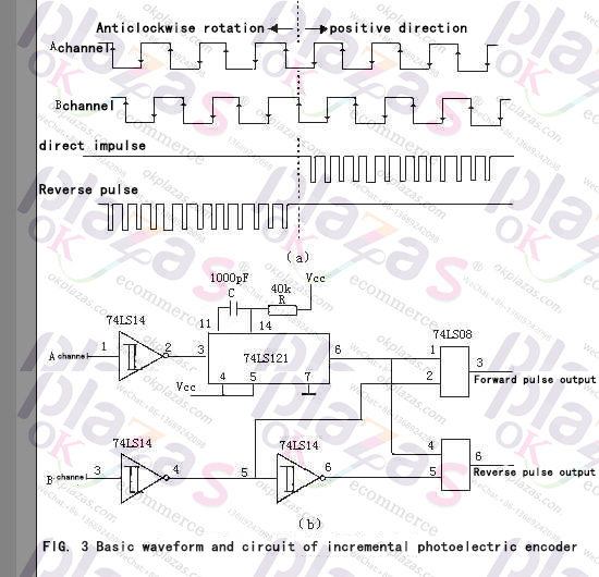
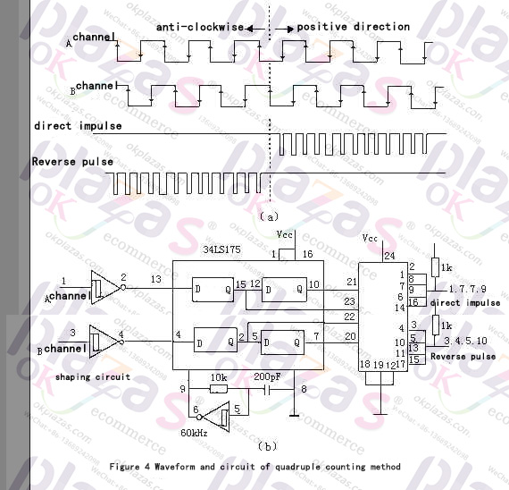
Figure 4 is a quadruple frequency subdivision circuit that can prevent false pulses and improve resolution. Here, a D-type flip-flop with memory function and a clock generating circuit are used. It can be seen from Figure 4 that each channel has two D flip-flops connected in series, so that in the interval of the clock pulse, the two Q terminals (such as the second and seventh pins of the 74LS175 corresponding to channel B) maintain the first two clock periods If the input state of the two is the same, it means that there is no change in the clock interval; otherwise, the direction of its change can be judged based on the relationship between the two, thereby generating a'forward' or'reverse' output pulse. When a channel changes back and forth between'high' and'low' due to vibration, it will alternately generate'forward' and'reverse' pulses, which can eliminate their influence when the two counters are replaced by the sum (below The reading of the instrument will also involve this). It can be seen that the frequency of the clock generator should be greater than the maximum possible vibration frequency. It can also be seen from Figure 4 that in the original period of the pulse signal, four count pulses are obtained. For example, an encoder with 1000 pulses per revolution can generate 4000 pulses with 4 times the frequency, and its resolution is 0.09°. In fact, these types of sensor products currently encapsulate circuits such as the amplification and shaping of the output signal of the photosensitive element and the sensing detection element, so as long as the subdivision and counting circuit are added, an angular displacement measurement system can be formed (74159 is 4- 16 decoder).
-
The principle and application field of Autonics panel products (handling)
 June 12, 2021
 -
New product launch SRH1 series single-phase SSR with integrated heat sink
 June 12, 2021
 -
New product launch SRH1 series single-phase SSR with integrated heat sink
 June 12, 2021
 -
Otto protection grade IP69K new product launched Ø18mm cylindrical (SUS316L housing) photoelectric sensor BRQT series
 June 12, 2021
 -
Autonics adds shading motion mode sensor
 June 12, 2021