Principle structure diagram of photoelectric encoder
Principle structure diagram of photoelectric encoder
Principle structure diagram of photoelectric encoder
Incremental photoelectric rotary encoder
The so-called encoder is a device that converts a certain physical quantity into a digital format. The function of the encoder in the motion control system is to convert parameters such as position and angle into digital quantities. Various types of encoders can be formed using mechanisms such as electrical contact, magnetic effect, capacitance effect, and photoelectric conversion. The most common encoder in motion control systems is the photoelectric encoder.
According to their use, photoelectric encoders are divided into rotary photoelectric encoders and linear photoelectric encoders, which are used to measure rotation angle and linear size respectively. The key component of the photoelectric encoder is the photoelectric encoding device. In a rotary photoelectric encoder, it is a circular codewheel (codewheel or codedisk), while in a linear photoelectric encoder, it is a straight-edge code strip. The code wheel and the yardstick can be made of metal, glass, polymer and other materials according to the needs of use and cost. The principle is to generate a digital optical signal representing the moving position during the movement.
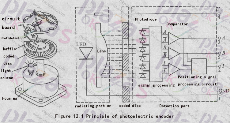
Figure 12.1 can be used to illustrate the principle of a transmissive rotary photoelectric encoder. A combination of light-shielding and light-transmitting parts formed according to certain coding rules is engraved on the code disc concentric with the measured axis. On one side of the code ring is a light-emitting diode or incandescent light source, and on the other side is a photoelectric device that receives light. With the rotation of the measured axis, the code disc produces discontinuities in the light beam passing through the code disc. Through the reception of photoelectric devices and the processing of electronic circuits, the output of specific electrical signals is generated. After digital processing, position and speed information can be calculated.
What I said above is the principle of transmissive photoelectric encoder. Obviously, photoelectric encoders can also be made using the principle of light reflection.
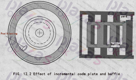
The code disk of the incremental encoder is shown in Figure 12.2. On modern high-resolution code discs, the light-transmitting and shading parts are very thin slits and lines, so they are also called circular gratings. The angle between adjacent slits is called the grating pitch angle, and the light-transmitting slits and the light-shielding part each occupy approximately 1/2 of the grating pitch angle. The resolution of the code disc is expressed in CPR-counts per revoluTIon, that is, the number of pulses that can be generated in the photoelectric detection part when the code disc rotates once. For example, if the CPR of a code disc is 2048, the distinguishable angle is 10, 311.8". On the code disc, a special slit (or a group) is often arranged to generate an index or zero position. (zero) signal. The measurement device or motion control system can use this signal to generate zero return or reset operations.
From the principle analysis, the electrical signal output by the optoelectronic device should be a triangular wave. However, due to the light diffraction caused by the gap between the moving part and the stationary part and the characteristics of the photoelectric device, the waveform obtained is similar to a sine wave, and its amplitude has nothing to do with the resolution of the code disc.
In the design of Figure 12.1, six groups of such baffle and photoelectric device combinations are arranged, two of which are used to generate index pulse signals I (Z in some literature). The other four groups, due to the arrangement of positions, produce 4 quasi-sine wave signals with a phase difference of 90°, called A, B, A, and B respectively. Send A and A with a phase difference of 180° to the two input ends of a comparator, and then a square wave signal A with a duty cycle of 50% is obtained at the output of the comparator. In the same way, square wave signal B can also be obtained from B and B. In this way, through the special arrangement of the position of the photoelectric detection device, two-channel photoelectric pulse output signals A and B are obtained (see Figure 12.3). These two signals have the following characteristics:
(1) The duty cycle of both is so%; Figure 12.3 The formation of dual-channel signals
(2) If the A signal leads the B signal by 90° in phase when rotating in one direction, the B signal leads the A signal by 90° in phase when the direction of rotation is reversed.
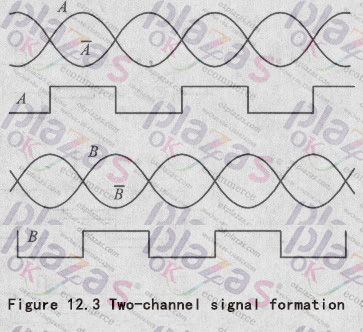
The characteristics of this dual-channel signal provide conditions for the improvement of measurement resolution and the acquisition of direction signals.
There are four special moments in square wave signals A and B with a duty cycle of so%, which are the leading and trailing edges of their waveforms.
The signals before and after the two signals are evenly distributed at 90° in one cycle of the waveform. Take these edge signals out and use them to obtain 4 times the frequency pulse signal, so that the resolution of the photoelectric encoder can be increased to 4 times.
Figure 12.4 is a processing circuit composed of digital circuits, in which Schmitt input inverters, exclusive OR gates, OR gates and D flip-flops are used. The waveforms of various parts in the circuit are shown in the figure, separated by a dotted line to indicate the waveforms in two cases of forward rotation and reverse rotation. It can be seen that the circuit produces a 4-fold frequency counting signal and a direction signal. Using these signals together with positioning pulses, the electronic circuit can determine the position of the motion system by counting the pulses. A counter can be used to increase the number when the shaft rotates in a certain direction, and decrease when it rotates in the opposite direction, so that the absolute position memory can be maintained without power failure.
Axis position indication of telescope
Figure 3.17 The working principle diagram of (a) code disc and (b) encoder of an eight-bit encoder
Modern industry has provided a series of axis angle position indicating devices for the axis angle system of the telescope. These devices include photoelectric encoders, circular induction synchronizers and grating rulers.
(1) Photoelectric encoder
The photoelectric encoder is a kind of binary photoelectric position indicator. Its basic principle is to obtain the binary digital signal of the angle position through the photoelectric element with different equally divided light and dark stripes, and finally decode the absolute value or relative value of the angle position. The code pattern of an absolute encoder is always unique, and this code pattern gives the position of the length or angle. The photoelectric encoder is composed of a light source, a code disc and a photoelectric receiver. The code disc is the most important part of the encoder. Figure 3.17 is an eight-bit encoder's code disk and encoder working principle diagram. The code disc here is a natural code disc. The code pattern of the absolute encoder has many forms. A code disc called Gray Code is particularly suitable for optical encoders (see Figure 3.18(a)). This kind of code disc only changes one digit every time it enters, and it is not easy to cause code errors.
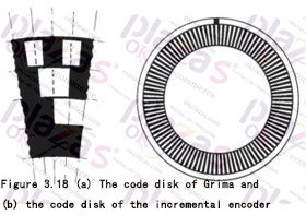
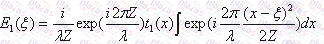
Figure 3.19 The working principle of incremental encoder code disc pulse information subdivision, the figure z represents the zero position
Another type of photoelectric encoder is incremental encoder. The code disk of the incremental encoder is shown in Figure 3.18(b). Its code wheel is composed of light and dark stripes. Generally speaking, incremental encoders with the same resolution accuracy are much cheaper than absolute encoders. Incremental encoders also have some methods to improve resolution accuracy. Usually the incremental grating code disc has four engraved tracks, two of which are light and dark stripe codes, and the other two are power source brightness indicator codes. The two stripe codes are staggered with each other, so that the encoder of the code disc can not only give the angle and size of the code disc movement, but also the direction of the code disc movement. At the same time, when the square wave pulse information of the grating code disc is input into the clockwise and counterclockwise up/down counters, the square wave information of the two stripe codes can be decomposed into one, two or four times the fine signal. Improve the resolution of the encoder. If the quality of the grating code disc is good, this fine four times the signal can be accurate to one-half of each signal pulse.
In order to obtain finer resolution, a method using a grating read head can achieve this goal. (See Figure 3.20) At this time, a small sub-grating is added behind the rotating grating. When the coherent light is irradiated on the grating disc, the light intensity on the sub-grating surface is (leki, 1999):
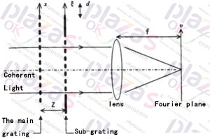
Figure 3.20 Working principle diagram of sub-grating code disc subdivision in incremental encoder (leki, 1999)
Where t1 is the projection rate of the grating. If the period of the first grating is p, the period of the second grating is also p. Using w as the spatial frequency on the focal plane, the light energy on the focal plane is:
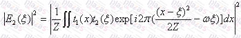
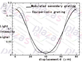
Figure 3.21 The relationship between the light intensity signal subdivided by the sub-grating code disc and the displacement in the incremental encoder, A.U means any
Unit (leki, 1999) Reprinted with permission from Taylor & Francis, Inc..
When M=0, the light energy of this signal can be expressed as a series. If only the first two items are taken, the light energy of the focal point is the cosine function of. In this way, through electrical subdivision, we may also obtain finer resolution accuracy. In practical applications, four groups of sub-gratings can be used to simultaneously use the upper and lower sets of stripes to improve the accuracy of electrical subdivision. However, as shown in Figure 3.21, the focal energy of the periodic grating is not a true cosine curve, so if the modulated sub-grating as shown in Figure 3.22 is used, the focal energy is a true cosine curve, and the resolution accuracy after subdivision will More accurate. In addition, using the method of modulating parallel light sources, using two surface light sources with different areas can also make the focal energy a correct cosine function. By applying a combination of incremental gratings with different resolutions, the sine and cosine values of different frequencies can be obtained, so that an absolute encoder with very high precision can be made. Generally, such high-precision encoders always have multiple code channels, which are DC reference codes and three to fifteen-digit sine and cosine codes.
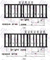
Figure 3.22 The specific grating dimensions of the two modulated sub-gratings of the incremental encoder (leki, 1999)
The precision of modern grating technology can also greatly improve the precision of photoelectric encoder. A 16-bit incremental encoder, such as adding a 16-bit absolute code pattern to its code disc, by imaging two adjacent stripes of the incremental code at the same time, it will give the precise position of the code disc, so that 24 The accuracy of absolute encoders above digits is a very important technological development.
(2) Circular induction synchronizer
Another similar shaft angle encoder device is a circular induction synchronizer. Unlike the photoelectric encoder, the circular induction synchronizer is an analog device. The change of each value is continuous, not jumpy. The basic principle of the circular induction synchronizer is shown in Figure 3.23. It consists of a stator and a mover. Its mover has only one coil, and on its stator, there are two coils that make up two poles. The angle between each of its coils is degrees. When the AC voltage is input into the mover and the axis of the mover deviates from the zero point of the stator by a certain angle, different amounts of current will be generated in each coil on the stator. As shown in Figure 3.24, there are:
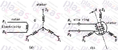
Figure 3.23 Basic principle of circular induction synchronizer
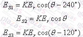
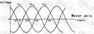
Figure 3.24 The output voltage in each coil on the stator of a circular induction synchronizer
Where is a proportional constant. If the coils on the stator are connected to each other as shown in Figure 3.23, the following current will be generated on the stator:
Using the characteristic of the circular induction synchronizer, it can be used to measure small angle changes. In order to determine the absolute position of the angle when using a circular induction synchronizer, a coarse code disc is also added. Comparing the photoelectric encoder, the circular induction synchronizer has the following advantages: (a) The coil fixed disk is cheaper, (b) the environmental requirements are lower, and it can be used in occasions with temperature changes and vibration.
(3) Encoder application and other angle measurement methods
The application of photoelectric encoder should adopt digital-to-analog conversion device in the control loop, and the circular induction synchronizer can be directly used for the control of synchronous drive. However, both of them can achieve absolute or incremental indication of the angular position of the shaft. Their position accuracy is high, error repeatability is good, but high-digit indicators are more expensive. The axis angle indication method of grating tape ruler and Moore fringe is newly developed in recent years. This method is especially suitable for large-aperture telescopes. The accuracy of this kind of grating tape ruler is about less than 1 micron. Generally, it is evenly pasted on the edge of the large driving wheel, and the moiré fringe gives high resolution accuracy. The disadvantage of the grating tape ruler is that it cannot guarantee the consistency of all stripes, which requires the use of a list method to be corrected in computer control. Grating tape rulers are often used for absolute calibration of positions in telescopes.
The absolute positioning accuracy of the telescope is for the requirements of accurate guiding and positioning, while the incremental positioning is for the requirements of precise guiding. Therefore, the incremental encoder requires higher resolution accuracy. The absolute encoder can be directly connected with the telescope drive shaft, at this time the position indication has no other error factors. But sometimes because the number of bits of the encoder is low or the telescope drive shaft needs to pass light, the encoder can also be installed on the first-stage gear. At this time, the resolution accuracy of the encoder is enlarged, but at the same time the error of the gear will also affect the accuracy of the absolute value of the angle. This error has a great influence on the absolute position calibration. However, in recent years, many telescopes have adopted incremental magnification indicating devices with high resolution accuracy, and other devices with excellent repeatability, such as high-sensitivity level gauges or special grating lines to provide the absolute zero point of the axial angular position. This eliminates the need for expensive absolute encoders. In some newer telescopes, a precision electromagnetic switch is used as the encoder of the absolute position of the shaft angle. The repeatability accuracy of this electromagnetic switch is about 1 micron. In this design, a precision electromagnetic switch is installed every 10 or 15 degrees. Between each precision electromagnetic switch, an incremental encoder is used, and even a friction surface can be used to drive a low incremental encoder. This design is cheaper than other designs. All kinds of encoders must be installed correctly to give full play to their resolution accuracy. When the encoder is connected to the shaft, the most important thing is to avoid applying any force and moment on the encoder shaft. Therefore, the coupling of the encoder should have relatively low strength in the axial and radial directions, and high strength in the circumferential direction.
For the new type of six-pole platform telescope, some also installed an angle measuring device called a fiber resonant gyroscope. A fiber resonant gyroscope includes three fiber loops in total. A beam of light is emitted from a laser diode with a very small bandwidth to one end of an optical fiber. At the same time, the end of this optical fiber winds back to the starting end and couples with the optical fiber at the starting end through an optical coupler to form an optical coupling. There are loops through which light passes in all directions. In the middle of this loop, there is another optical coupler to make the first loop and the second optical fiber ring realize coupling. At the same time, there is a third optical coupler on the opposite side of the second optical fiber ring to realize the coupling of the second optical fiber ring and the third optical fiber loop. The third optical fiber loop is an open loop loop, and both ends are connected to the detector. In this system, if all loops and couplings are fixed and the two couplings are located exactly at the symmetry point of the loop in the second optical fiber loop, it will resonate with a specific wavelength of light. When the second circuit has a small corner relative to the first circuit, the light path in one direction will increase in the second circuit, and the light path in the other direction will decrease, so the new system will Resonance occurs at two different frequencies. Compared with the original resonance frequency, one of the frequencies is larger and the other is smaller. By measuring the change of the resonance frequency, the angle change can be understood to achieve the purpose of angle measurement.
-
The principle and application field of Autonics panel products (handling)
 June 12, 2021
 -
New product launch SRH1 series single-phase SSR with integrated heat sink
 June 12, 2021
 -
New product launch SRH1 series single-phase SSR with integrated heat sink
 June 12, 2021
 -
Otto protection grade IP69K new product launched Ø18mm cylindrical (SUS316L housing) photoelectric sensor BRQT series
 June 12, 2021
 -
Autonics adds shading motion mode sensor
 June 12, 2021