Programming ideas for rotary encoder
Programming ideas for rotary encoder
When the rotary encoder is used for angle positioning or measurement, it usually has A, B, Z three-phase output. Phase A and Phase B output a square wave with a 50% duty cycle. Each time the encoder rotates, phase A and phase B output a fixed number of pulses. When the encoder rotates in the forward direction, phase A is ahead of phase B by a quarter of a cycle; when the encoder rotates in the reverse direction, phase B is ahead of phase A by a quarter of a cycle. The phase difference between the A-phase and B-phase output square waves is 90°. The Z phase outputs a pulse every time the encoder rotates one round. Since the encoder outputs a fixed number of pulses for each revolution of the A-phase and B-phase, each output pulse of the A-phase or B-phase indicates that the encoder has rotated a fixed angle. When the Z-phase outputs a pulse, it means that the encoder has rotated once. Therefore, the rotary encoder can measure angular displacement and displacement direction.
What we usually use is an incremental encoder, which can directly input the output pulse signal of the rotary encoder to the PLC, and use the high-speed counter of the PLC to count the pulse signal to obtain the measurement result. Different types of rotary encoders have different phases of output pulses. Some rotary encoders output A, B, and Z three-phase pulses, some only have A and B phases, and the simplest is A phase.
The encoder has 5 leads, of which 3 are pulse output lines, 1 is the COM terminal line, and 1 is the power line (OC gate output type). The power supply of the encoder can be an external power supply, or directly use the DC24V power supply of the PLC. The “-” terminal of the power supply should be connected to the COM terminal of the encoder, and the “+” terminal should be connected to the power terminal of the encoder. The COM terminal of the encoder is connected to the PLC input COM terminal. The A, B, and Z phase pulse output lines are directly connected to the input terminal of the PLC. A and B are pulses with a difference of 90 degrees. The Z-phase signal can only be rotated once the encoder A pulse is usually used as the basis for zero point. Pay attention to the response time of PLC input when connecting. The rotary encoder also has a shielded wire, which should be grounded when using it to improve anti-interference.
Encoder-----------PLC
A, B, Z are respectively connected to the input points of the PLC (according to the provisions of the speed counter HSC)
+24V------------+24V
COM------------- -24V-----------COM
The application circuit of the rotary encoder is:
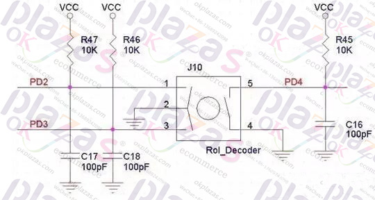
Among them, the capacitance of 100pF is used for debounce, but it is better to add software debounce when processing software to prevent misjudgment. The most commonly used software debounce is delay and continuous sampling multiple times, which will not be detailed here.
The output waveforms of A and B are
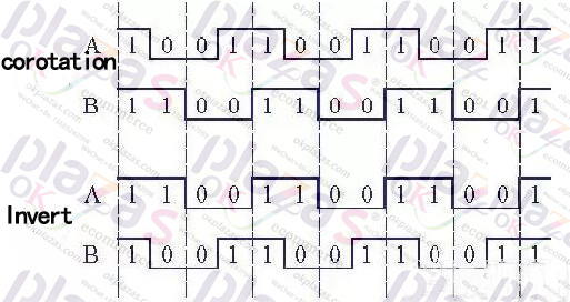
The output waveform chart shows that the timing of each motion cycle is
The static state is 11 or 00, the result of A XOR B is 0 (Note 1)
The one-chip computer can use the timer interrupt to detect the state of A and B, the interruption time can be between 5~20ms.
When A^B=0 is detected, it is a static state, and the states of A and B are noted.
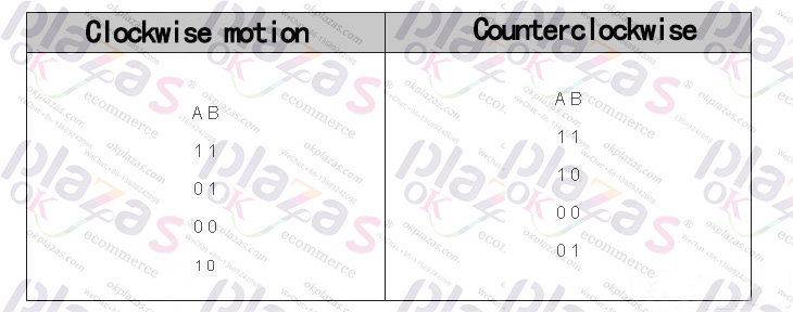
When A^B=1 is detected, it means there is rotation, read the state of AB, if AB is from 11 to 01 or
From 00 to 10, it is forward rotation, otherwise, if AB is from 11 to 10 or from 00 to 01, it is reverse.
This method is relatively simple and reliable, and can detect a single rotation and a rapid rotation.
Note 1: Exclusive OR operation
The XOR operation method is a binary operation. In C language, A^B is used to represent A XOR
B:
1^1=0
0^0=0
1^0=1
0^1=1
Both are equal to 0 and unequal to 1.
-
The principle and application field of Autonics panel products (handling)
 June 12, 2021
 -
New product launch SRH1 series single-phase SSR with integrated heat sink
 June 12, 2021
 -
New product launch SRH1 series single-phase SSR with integrated heat sink
 June 12, 2021
 -
Otto protection grade IP69K new product launched Ø18mm cylindrical (SUS316L housing) photoelectric sensor BRQT series
 June 12, 2021
 -
Autonics adds shading motion mode sensor
 June 12, 2021