Rotary encoders are mainly used in the following fields
Rotary encoders are mainly used in the following fields
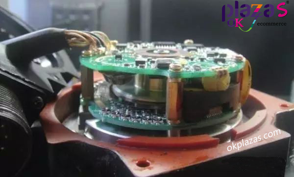
In practical engineering applications, the rotary encoder usually has the function of detecting the motor speed, equipment operating position and stroke in the automation system. According to the purpose, it can be divided into two types: speed encoder and stroke encoder. At present, rotary encoders are mainly used in the following fields:
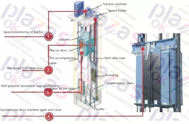
Elevator field-both the speed adjustment of the elevator and the position control of the car require very precise signals. The encoder can provide reliable and accurate position signals and speed signals in the elevator control to complete the normal operation of the elevator;
Vector motor and servo motor field-vector motor and servo motor can perform speed, torque and position control in a wide range, all relying on the encoder on the motor output shaft;
Construction machinery field-large construction machinery has an increasing demand for reliable speed and position detection, especially in the heavy-duty vehicle industry. Encoders are widely used in electronic power steering systems, vehicle speed detectors and hybrid vehicles;
Industrial automation control production line field-the factory's automated production line needs accurate speed and direction information to ensure the normal operation of the motor;
Industrial robot field-each joint of the robot needs precise control to ensure the coordinated movement or walking of the whole robot, so each joint needs an encoder for coordinated control.
Oil and gas industry-the oil and gas industry is a high-risk industry that requires high-standard encoders with higher reliability and better sealing. It is mainly used for speed measurement of drill floor motors, turntables and sludge pumps. For example, the encoders on tankers are used Measure the flow rate and the amount of fuel added;
Application of rotary encoder in elevator field
When users choose elevators, the advantages of compact structure, high power density, maintenance-free and high power efficiency are playing an important role. For passengers to feel more comfortable and continuously improve quality, innovative and efficient drive systems are needed, including motors and control systems.
The technical basis of this innovative system is to provide a feedback system for the position value, so that the actual shaft speed of the motor can be determined in the control unit and the motor coil can be commutated when the phase is correct.

A rotary encoder is such a position feedback unit. During the operation of the elevator, the following signals are calculated in real time through the detection of the rotary encoder and the software: the position of the elevator floor, the position of the speed change point, and the position of the leveling point, so as to count the floors, send out the speed change signal and the leveling signal.
In elevator applications, the advantages of absolute rotary encoders are more prominent. Because this rotary encoder has high resolution and uses a pure serial transmission protocol (no additional incremental signals).
The absolute rotary encoder has N position values per circle and has high accuracy, which provides the required resolution for advanced and sensitive drive control systems. Through the high-quality scanning grating, and subdividing the scanning signal in the specially developed ASIC follow-up electronic circuit, each circle can provide enough resolvable position values, which brings enough positions for the drive control system. And a larger clock frequency can provide dynamic motor control fast enough-this is directly related to the passenger's elevator riding experience.
In addition, the most significant advantage of the absolute encoder for elevator users is that it can provide more features in the background. The designated position value (such as the zero position) transmitted through the bidirectional serial interface simplifies the work of the control unit and enables the control unit to efficiently provide a commutation signal for the motor magnetic field at the correct phase to ensure the best torque. Due to the high resolution of the rotary encoder, almost any motor with the number of pole pairs can be easily adapted to this correct phase position assignment. In other words, a rotary encoder is suitable for a large number of motors with very different designs and structures.
Another advantage of the bidirectional interface is the communication between the motor and the control unit. On the one hand, it can transmit position values, on the other hand, it can also transmit parameters related to specific encoders and motors. This information is read from the EEPROM storage area of the rotary encoder to the control unit during the system startup phase and system configuration. The factory can use this function to pre-install relevant parameters, shorten the debugging time for the first use and avoid possible errors in manually inputting parameters to the drive system.
Not only that, this interface also has a monitoring function, which makes the elevator more reliable. The advanced electronic circuit design of the rotary encoder also provides signal processing capabilities for the temperature sensor. In addition to the temperature sensor in the encoder, this encoder also allows to connect the temperature sensor circuit board at the motor coil and perform temperature signal processing and transfer the processed data transmission protocol to a higher level of electronic circuits. In addition, the diagnostic value in the form of significant figures generated in the encoder electronic circuit is also transmitted through this interface, and the encoder's functional redundancy judgment is performed. When the critical value is reached, necessary protective measures need to be taken to avoid unexpected downtime for maintenance.
The absolute rotary encoder with subdivision and bidirectional serial interface is the ideal choice for elevator motor control system. Its data transmission capabilities, such as absolute position value transmission capability, high resolution, short cycle time for transmitting digital position values, and better connection technology enable it to improve the performance of the control system, and its monitoring and diagnostic functions help users to prevent Sexual maintenance and regular maintenance.
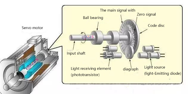
Application of rotary encoder in the field of servo motor
I believe that all engineers who do mechanical equipment know that servo motors, stepper motors and brushless motors are the most common types of precision mechatronic motors. These motors have a common feature that they all use drivers to give numbers. The signal is given to the motor to make the motor operate according to the established mode. Controllable, programmable, and high precision are the main features of these motors. However, some customers' equipment requires precise positioning, such as precise positioning of speed, precise positioning of displacement, etc. This cannot be achieved by motors and drivers alone. At this time, you need to install an encoder.
Servo motor encoder is a high-precision electromechanical component that monitors and feeds back the direction and position of the motor. If you want to achieve basic synchronization between servo and frequency conversion, a control interface is needed to control
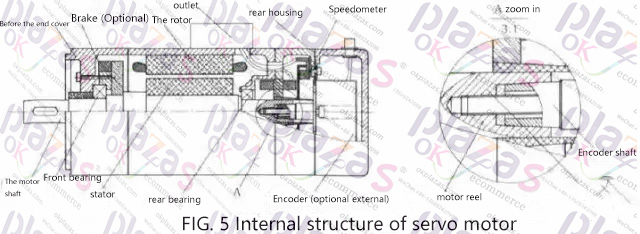
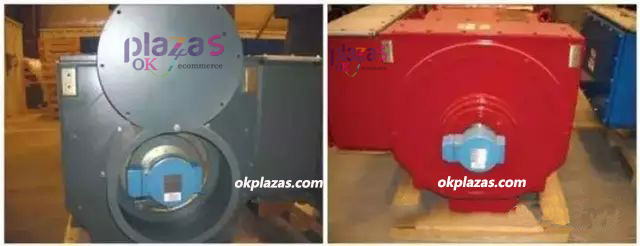
The rotor inside the servo motor is a permanent magnet. The U/V/W three-phase electricity controlled by the driver forms an electromagnetic field. The rotor rotates under the action of this magnetic field. At the same time, the encoder of the motor feedback signal to the driver, and the driver compares the target with the feedback value. Compare the values and adjust the angle of rotation of the rotor. The accuracy of the servo motor is determined by the accuracy of the encoder (number of lines).
Matters needing attention in servo motor encoder measurement
Encoder signal measurement and processing is an important issue for servo motor control. The position, speed and acceleration of the motor rotor are all derived from the encoder signal. After the encoder pulse signal is measured and processed, accurate information will be obtained, which is the basis of control. Otherwise it will mislead control.
Usually encoders have A, B, Z pulse signals, and some have U, V, W pulse signals in addition. A, B signal: It is the motor position pulse signal. The direction of rotation can also be distinguished by the phase difference of the A and B signals. The frequency of the A and B signals are the same, the phase difference is 90, and their duty ratios are both 50%. The rising and falling edges of the A and B signals can be processed into pulses through the circuit. In one A pulse period, 4 Pulses. Z signal: Zero signal, every time the motor rotates, a Z pulse signal will be generated at the zero position. In order to make the Z signal more reliable, it is generally stipulated that the rising edge of the Z signal can only be determined when the A and B signals are high. The Z signal is valid. U, V, W signals: used to judge the starting position.
Note for A and B signal measurement:
The A and B signals are processed into pulses of 4 times the frequency, which appear at 0, 90, 180, and 270 of the A period, respectively. But this ideal state does not exist, usually the phase difference between A and B pulses is not exactly 90, and the high level and time of the A and B pulses are not exactly equal. You can refer to the data given by the encoder manufacturer. That is to say, the time intervals of the 4 pulses are not equal. If the T method is used for measurement, the actual rotation speed will not change but the rotation speed measurement value will fluctuate. This is a problem that must be avoided.
way of solving the problem:
1. When doing T method measurement, two adjacent pulses cannot be used, but the same edge of the same signal should be used. To explain, the so-called same signal is for example A signal, and the same edge is for example rising edge, that is, the T method is measured from the last rising edge of A to this rising edge of A. You can also use the falling edge to the falling edge of A, or the same edge of B. The advantage of this is that the accuracy is guaranteed, but the disadvantage is that the period is 4 times that of the adjacent edge, which increases the delay.
2. Measure the distance of each edge in advance, calculate the correction coefficient, and make real-time correction. The advantage of this is that the delay is only 1/4 of the previous scheme, but the disadvantage is that the edge-to-edge accuracy cannot be ensured, because the time difference between adjacent pulses may vary with the angle of the motor, and it may also vary with the speed when the vibration is strong. change. Accuracy cannot be fully guaranteed.
Precautions when measuring Z signal:
Once the Z signal is interfered and misjudged, it will cause synchronization failure, and the motor current will increase rapidly and cause serious consequences. Therefore, special attention should be paid to anti-interference processing for Z signal. The Z signal increases the anti-interference ability through the correlation between A, B, and Z. This method reduces the possibility of interference to 1/4 of the original. However, this measure is not enough in an environment with severe interference and high frequency chopping.
Window method:
The window method is to open a window near the zero position, and only the Z signal that appears in this window and satisfies the level relationship between A, B and Z at the same time is considered as a Z signal. Z signals generated outside the window are not recognized. For example, if an encoder with 2500 lines per circle is used, the number of quadrupled frequency pulses generated per circle is 10,000. When the pulse reaches between 9700 and 10300, the Z signal is valid, and the Z signal is not recognized at other times.
Application of Rotary Encoder in Road Inspection Vehicle
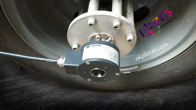
At present, with the continuous advancement of my country's urbanization and infrastructure construction, more and more roads are being planned, constructed, and continuously completed and put into use. In order to ensure the safety and smoothness of traffic, it is essential to detect road defects and flatness. In this regard, rotary encoders are used in road inspection vehicles. In the detection of wheel speed, it has become a weapon for road inspection and maintenance through its excellent detection accuracy.
As the number and types of roads continue to increase, effective inspection and management of them has also become an issue. For different types of roads such as expressways, graded highways, urban roads and airport runways, whether cracks, cracks and other road diseases appear, or the flatness does not meet the corresponding standards, it may affect its normal functioning or even cause serious problems. The hidden dangers. In the current wave of informatization, it is even more necessary to combine road inspection work with an informatization management platform to store, manage and utilize various road data indicators.

In response to this demand, a new type of road inspection vehicle has emerged, which has become the best tool to solve the road inspection problem. This inspection vehicle integrates and applies modern information technology, and is equipped with advanced sensors, image acquisition systems, on-board computers and other components on the vehicle platform. Under the normal driving state of the vehicle, it can automatically complete the collection, analysis, classification and storage of road surface images, road shapes, three-dimensional images of road facilities, flatness and road geometric parameters, and even automatically generate inspection reports and maintenance plans.
Application of rotary encoder in metallurgical production line
The hot rolling production line is one of the important production lines in the metallurgical industry. Most of its mechanical devices are driven by AC speed-regulating motors, and the speed-regulating method is mainly frequency-variable.

The hot rolling production line is generally composed of a slab warehouse, heating furnace, rough rolling, finishing rolling, coiling and transportation chain. As an important equipment of the rolling line, the flying shear system can be installed on the rolling production line of a continuous rolling mill to cut the head and tail of the rolled piece or cut the rolled piece to a fixed length; the use of flying shear is beneficial The steel rolling production is rapidly developing in the direction of high speed and continuity.
Therefore, it is one of the important means for the development of steel rolling production. The theory of rolling mill rolling: rolling is a material that uses the friction force of the rotating rolls to drag the rolling piece into the rolls, and at the same time relying on the pressure applied by the rolls to make the rolling piece compress and deform between two or more rolls processing method.
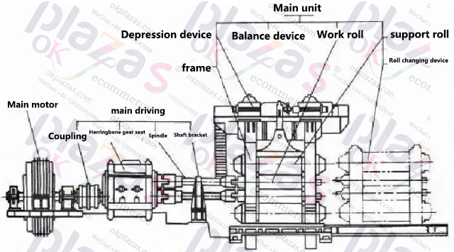
The main drive system of the rolling mill adopts a fully digital speed regulation system. The speed controller contains a voltage loop, a current loop, and a speed loop. The speed loop feedback element uses an incremental encoder. Incremental heavy-duty large shaft sleeve rotary encoder and speed control device have better application effect, stable speed control, fast speed response, and high speed regulation accuracy. The lower pinch roller is equipped with an encoder to control the speed of the stick to synchronize the flying shear and the pinch roller mill.
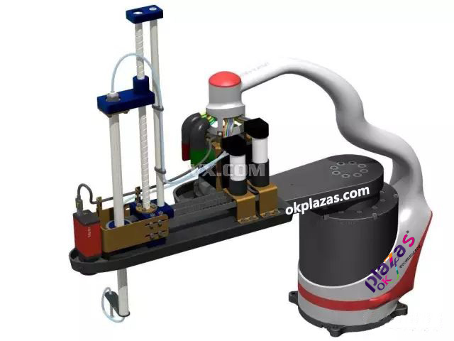
Application of rotary encoder in robotic arm in automation field
Widely used in the continuous development of the automation field, in precision measurement, measurement equipment, object positioning equipment, absolute encoders have been more and more widely used because of their absolute uniqueness, anti-interference, and no power-down memory. It is used in angle, length measurement and positioning control in various industrial systems and in robotic arms, and has great advantages in robotic arms.
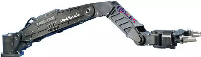
Generally speaking, the feedback of the position information of the robot arm in each dimension requires an absolute encoder to provide feedback. In the application of high-precision robotic arms, such as semiconductor automated robotic arms, you can also consider working with encoders, which can provide up to tens of digits of multi-turn position information and provide necessary feedback information for precise control of the robotic arm.
Some absolute rotary encoders can detect the motion information of 12,000 revolutions per minute, and the response is very sensitive; the motion speed and other parameters of the robot arm can be calculated by reading the position information. For the movement position of the multi-dimensional robot arm, the absolute encoder can be read by the main controller when it is powered on, which has great advantages for the incremental encoder.
For the design of mechanical arms, absolute encoders have the advantages of high precision, high sensitivity, small size, and modular design, which can be better applied to them.
In the application of multi-turn photoelectric absolute value encoder, because its position information does not require battery power supply or other storage, it can be easily read after the system is powered on. These advantages are unmatched by incremental encoders. Absolute encoders have the advantages of high precision, high sensitivity, fast response, small size, modular design, etc., which can be well used in gate opening control, robotic arms, and high-precision position control components.
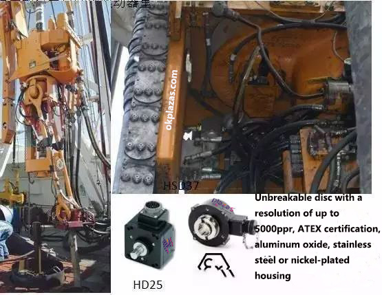
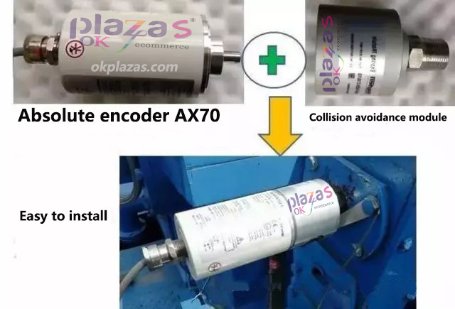
Application of rotary encoder in petroleum machinery products
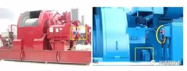
Top drive-magnetoresistive encoder-rotating drill pipe and drill bit. Motors and gear systems generally have an encoder installed to feed back speed and position to the drive.
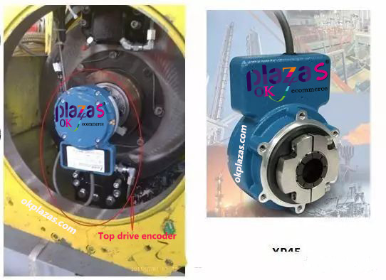
Top drive-photoelectric encoder
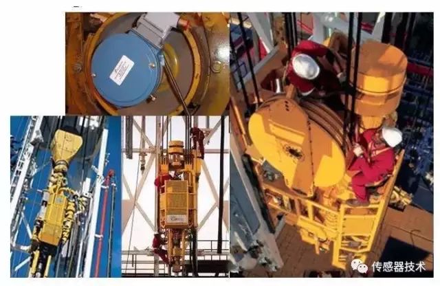
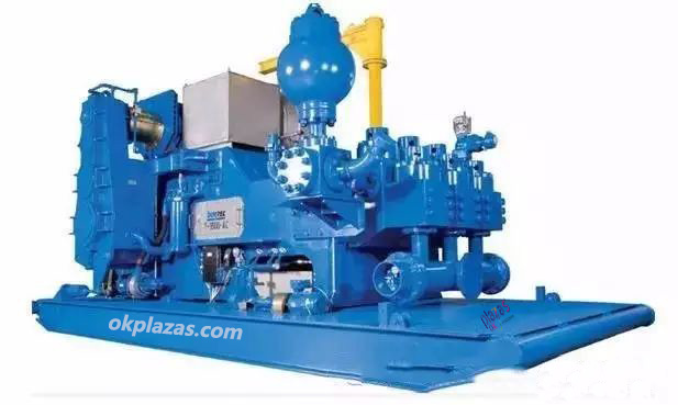
Winch and cement pump truck
Roller encoder
Mud pump-multi-motors are used in downholes for circulating mud. The motors use encoders for speed control to improve flow linearity.
-
The principle and application field of Autonics panel products (handling)
 June 12, 2021
 -
New product launch SRH1 series single-phase SSR with integrated heat sink
 June 12, 2021
 -
New product launch SRH1 series single-phase SSR with integrated heat sink
 June 12, 2021
 -
Otto protection grade IP69K new product launched Ø18mm cylindrical (SUS316L housing) photoelectric sensor BRQT series
 June 12, 2021
 -
Autonics adds shading motion mode sensor
 June 12, 2021