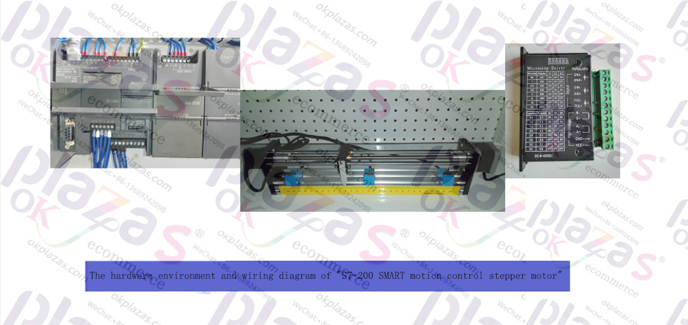
S7-200 SMART Motion Control Course hardware environment and electrical schematic diagram
S7-200 SMART Motion Control Course hardware environment and electrical schematic diagram
S7-200 SMART Motion Control Course hardware environment and electrical schematic diagram
"S7-200 SMART Motion Control Stepping Motor"
In this article, we introduce the hardware environment and electrical schematic diagrams used in the next course, which are the basis for subsequent programming and debugging.
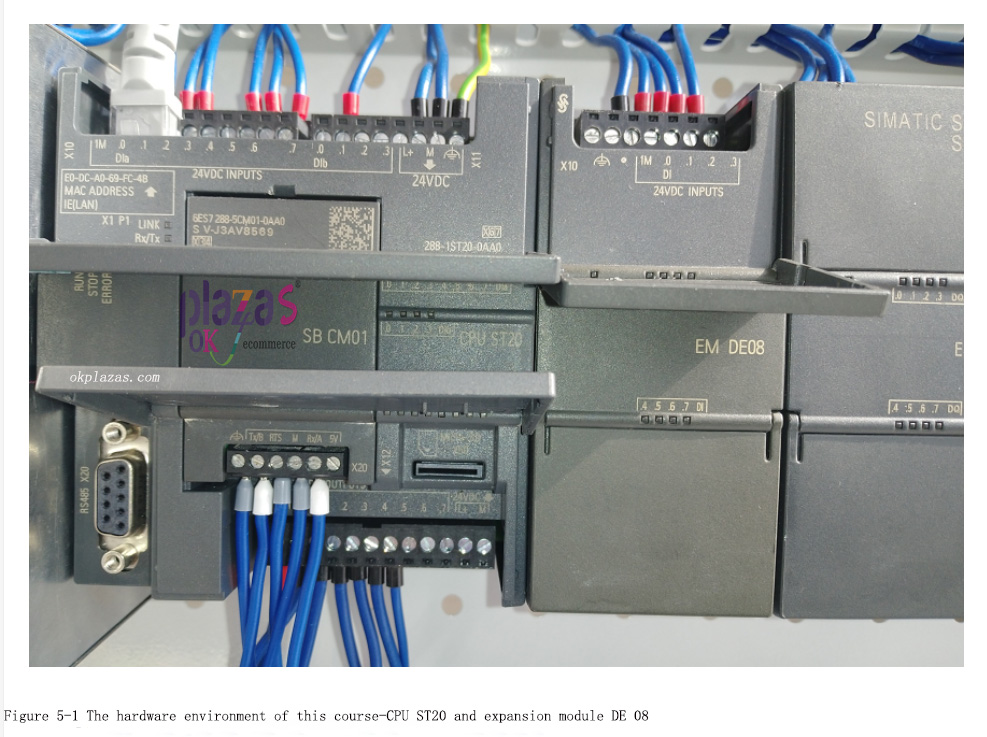
The CPU used in this course is Siemens S7-200SMART standard CPU ST20, in order to detect
The zero point and left and right limit signals of the sliding table are added with the expansion module EMDE08; a stepping driver with subdivision function is adopted; a stepping motor and an incremental encoder are installed on the experimental sliding table;
Below we will introduce in detail:
1. CPU ST20 and expansion module EM DE08
The CPU and expansion modules used in this course are shown in Figure 5-1:
Use the axis 0 of CPU ST20, Q0.0 is used to send PTO pulse signal, Q0.2 sends the direction signal of the motor, and Q0.4 sends the motor control/enable signal; these three signals are respectively connected to the PUL+, DIR+ and DIS+;
Use the high-speed counter 1 (HSC1) of the CPU ST20 to connect an incremental encoder for closing
Loop control, where I0.0 is connected to the A phase signal of the encoder, and I0.1 is connected to the B phase signal of the encoder;
The expansion module EM DE08 is used to connect the proximity switch signal on the sliding table, among which I8.0 is connected to the zero signal; I8.1 is connected to the left limit signal (LMT-); I8.2 is connected to the right limit signal (LMT+); The switch is NPN type, so the wiring mode of EM DE08 is: source input.
The so-called "SourcingInput" refers to connecting the common terminal of EM DE08 to 24
The positive pole of the V power supply, the current flows into the module from the common terminal, and then flows out of the channel of the module to the sensor. The external sensor connected by this wiring method is NPN type.
Corresponding to "source input" is "sink input". The so-called "drain input" refers to connecting the common terminal of EM DE08 to the negative pole of the 24V power supply, and the current flows from the sensor to the channel of the module, and then returns to the negative pole of the power supply from the common terminal of the module. Lina's external sensor is PNP type.
EM DE08 supports both source input and sink input. Because the proximity switch used in this course is of the NPN type, the source input wiring method is adopted.
2. Stepper driver
The stepper driver used in this course is shown in Figure 5-2:
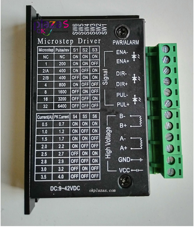
Figure 5-2 Stepper driver
The driver supports DC9~24V input voltage, supports 8 gears of current S4/S5/S6) and 7 gears of subdivision drive (S1/S2/S3), supports pulse (PUL+/PUL-), direction (DIR+/DIR-) and enable signal (ENA+/ENA-); can drive two-phase stepper motor;
The wiring of CPU and stepper driver is shown in Figure 5-3 (the picture contains the wiring of stepper driver and stepper motor):
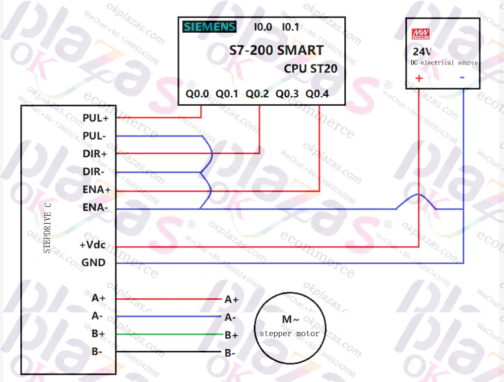
Figure 5-3 Wiring of CPU ST20 and stepper driver
3. Sliding table (including stepper motor, encoder, limit switch, etc.)
The sliding table used in this course is shown in Figure 5-4:
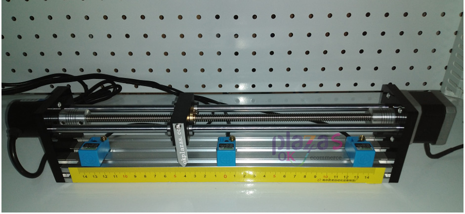
Figure 5-4 The appearance of the sliding table used in this course
The stepper motor used in the sliding table is a 42 series two-phase stepper motor, with a step angle of 1.8 degrees; rated current 0.5A; each rotation of the stepper motor, the screw rod moves 4mm; the lead wire of the stepper motor is A+, blue It is A-, green is B+, and black is B-; please refer to Figure 5-3 for the wiring of stepper motor and stepper driver.
The other end of the sliding table is an encoder, which is an A/B quadrature incremental encoder, NPN type, which sends out 600 pulses per revolution. The output signal line of the encoder is connected to the high-speed counter HSC1 of the CPU. The wiring schematic diagram is shown in Figure 5-5:
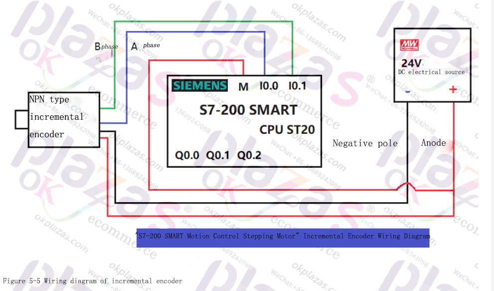
Figure 5-5 Wiring diagram of incremental encoder
There are left limit switch S2 (LMT-), zero switch S1 (Zero) and right limit switch S3 (LMT+) on the sliding table, all of which are of NPN type, connected to the input channel of the expansion module EM DE08, the wiring diagram is shown in the figure As shown in 5-6:
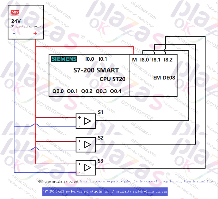
Figure 5-6 Wiring diagram of proximity switch
Well, this is the hardware environment and electrical schematic diagram used in this course, and subsequent courses are based on this. In order to facilitate the operation, we will add a control button box for the start and stop control of the motor.
-
The principle and application field of Autonics panel products (handling)
 June 12, 2021
 -
New product launch SRH1 series single-phase SSR with integrated heat sink
 June 12, 2021
 -
New product launch SRH1 series single-phase SSR with integrated heat sink
 June 12, 2021
 -
Otto protection grade IP69K new product launched Ø18mm cylindrical (SUS316L housing) photoelectric sensor BRQT series
 June 12, 2021
 -
Autonics adds shading motion mode sensor
 June 12, 2021