Schematic diagram of relay drive circuit
Schematic diagram of relay drive circuit
The principle and precautions of the relay drive circuit. The application of relays is becoming more and more extensive. The role of relays is mainly used to control current. At present, the common relays include general relays, automotive relays, power relays, etc. We will inevitably encounter Encountered all kinds of problems, such as the principle of the relay drive circuit and precautions, let me explain it to you.
The relay drive current generally requires 20-40mA or more, and the coil resistance is 100-200 ohms, so a drive circuit must be added. There are many ways to drive the circuit at present: transistors are used to drive relays, integrated ICs drive relays, and optocouplers drive relays.
The specific circuit of the transistor drive relay is as follows:
NPN transistor, PNP transistor
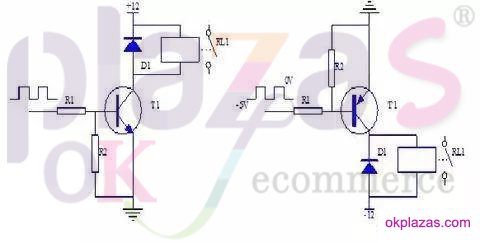
When the NPN transistor is driven: When the base of the transistor T1 is input high, the transistor is saturated and turned on, and the collector becomes low. Therefore, the relay coil is energized and the contact RL1 is closed.
When the base of the transistor T1 is input low, the transistor is cut off, the relay coil is cut off, and the contact RL1 is cut off.
The PNP transistor drive circuit is not currently used, so it will not be introduced here.
The role of each component in the circuit: The transistor T1 can be regarded as a control switch, and VCBO≈VCEO≥24V is generally selected, and the amplification factor β is generally selected between 120 and 240. . Resistor R1 mainly acts as a current limiter and reduces the power consumption of transistor T1. The resistance value is 2 KΩ. The resistance R2 makes the transistor T1 cut off reliably, and the resistance value is 5.1KΩ. Diode D1 reverses freewheeling to suppress surges. Generally, 1N4148 is enough. Integrated Circuit 2003 Drive Relay
Figures 1-7 on the left are signal input (IN), 10-16 are output signals (OUT), and 8 and 9 are integrated circuit power supplies.
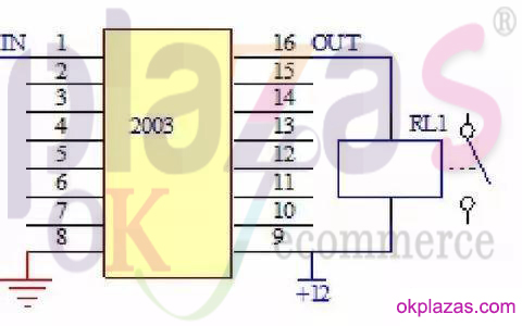
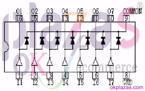
Working principle: According to the input and output characteristics of integrated circuit driver 2003, some people call it "driver", "inverter" and "amplifier" for short. Now the commonly used model is: TD62003AP. When the 2003 input terminal is high, the corresponding output port outputs low level, the relay coil is energized, and the relay contact is closed; when the 2003 input terminal is low, the relay coil is de-energized and the relay contact is disconnected; in 2003 The diode has been integrated to play the role of reverse freewheeling, so it can be directly used to drive the relay.
Optocoupler Drive Relay
R1 and R2 are current-limiting resistors. This circuit can be isolated because the input and output are completely isolated because of the function of the optocoupler, but the distance between the input and the output of the relay should be sufficient when designing
working principle:
1. When an input low level is given to the photocoupler, the photocoupler photodiode is turned on, the output is turned on, the relay 12V is turned on, and the relay output load works.
2. When an input high level is given to the photocoupler, the photocoupler photodiode is cut off, the output is disconnected, the relay 12V is disconnected, and the relay output load stops working.
-
The principle and application field of Autonics panel products (handling)
 June 12, 2021
 -
New product launch SRH1 series single-phase SSR with integrated heat sink
 June 12, 2021
 -
New product launch SRH1 series single-phase SSR with integrated heat sink
 June 12, 2021
 -
Otto protection grade IP69K new product launched Ø18mm cylindrical (SUS316L housing) photoelectric sensor BRQT series
 June 12, 2021
 -
Autonics adds shading motion mode sensor
 June 12, 2021