Siemens air circuit breaker 3WL interlock and connection circuit schematic diagram
Siemens air circuit breaker 3WL interlock and connection circuit schematic diagram
Siemens air circuit breaker 3WL interlock and connection circuit schematic diagram
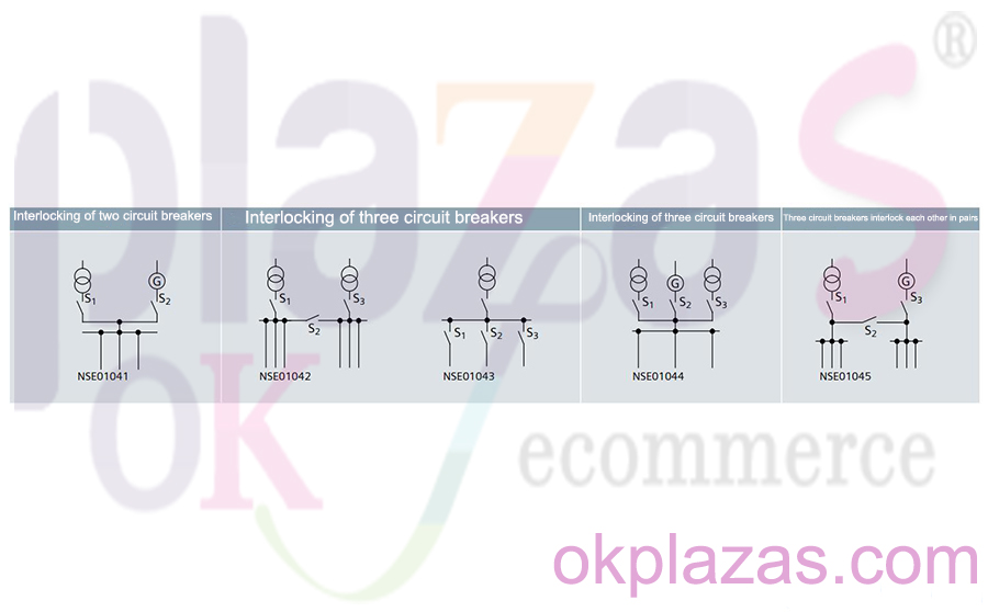
Siemens air circuit breaker 3WL interlock function
The mechanical interlocking module can be used for 1 or 2 Siemens 3WL circuit breakers, and can be easily adjusted according to the corresponding model. Fixed and withdrawable circuit breakers are fully compatible, so they can be used in combination. This is also applicable to 3WT and 3WN1 circuit breakers.
The air circuit breaker can be installed in a left-right arrangement or a vertical arrangement, and the distance between the circuit breakers only depends on the length of the steel cable (length: 2m/3m/4.5m). The use of steel cables can circulate interlock signals. For withdrawable circuit breakers, the interlock is only effective when the equipment is in the connected position. The mechanical life of the steel cables is 10,000 times.
The minimum requirements for the interlock function must be met in the switchgear:
●The steel cable must be laid as straight as possible;
●The bending radius of the steel cable must be greater than 500mm;
●The sum of all bending angles along the steel cable cannot exceed 640°;
●If the interlocking Siemens air circuit breaker is arranged vertically, the interlocking mechanism must be connected in series;
●When arranging interlocking circuit breakers, 2m or 4.5m steel cables should be installed to meet the above requirements;
●Before adjusting the interlocking device, the installed steel cable must be fixed (using cable ties, etc.);
●The switch cabinet should be wide enough to leave room for adjusting the interlocking device;
●When designing openings and openings in system components, the direction of the steel cable should not be changed or obstructed.
The circuit diagram of Siemens circuit breaker 3WL mutual mechanical interlock is shown below:
An example of the working principle of the regional optional interlock function in power distribution:
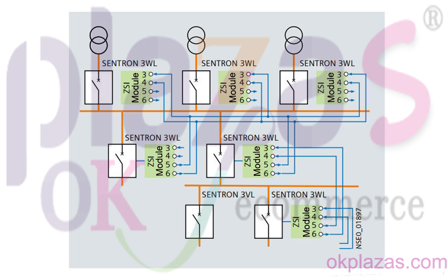
Siemens 3VL and Siemens 3WL circuit breakers for different short-circuit levels (levels) of high and low.
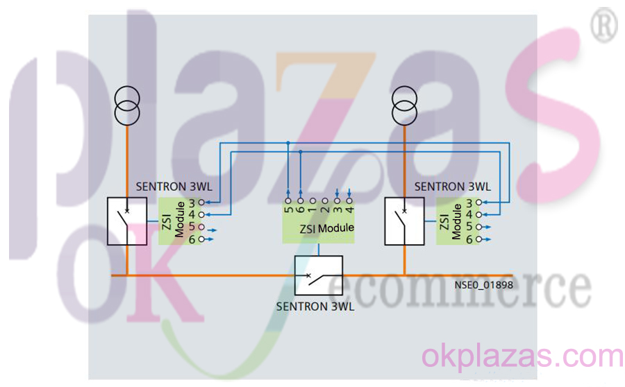
Using Siemens air circuit breakers, the wiring diagram of regional selective interlocking can meet the functions of multiple power feeders and outlet units.
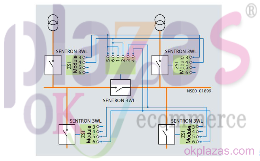
Regional selective interlocking function: use one tie switch and 3WL circuit breaker.
Siemens air circuit breaker 3WL connection circuit schematic diagram
The main circuit connection is the standard configuration, and all circuit breakers up to 5000A are equipped with the main busbar connection installed after the horizontal plate (for horizontal connection to the busbar). The exception is the Frame II circuit breaker with the maximum rated current of 4000A. The circuit breaker with the maximum rated current of 6300A and the Frame II air circuit breaker with the maximum rated current of 4000A are all equipped with a vertical main busbar connection (for vertical installation of the busbar).
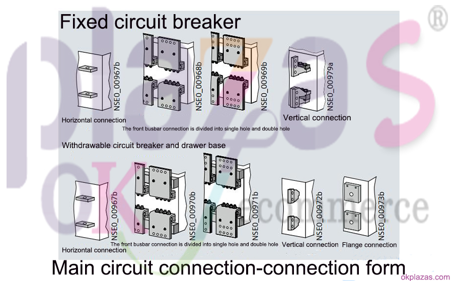
The following options are available for up and down line entry:
●Front connection, single hole (busbar vertical installation);
●Front board connection, double holes (DIN 43673 holes) (vertical installation of the busbar);
●Vertical behind the board (the busbar is installed vertically);
●Connecting flange (used to directly connect to the drawer base, up to 4000A).
Connect the auxiliary circuit terminals according to the installation form:
● Withdrawable type: The internal auxiliary circuit terminal is connected to the plug on the Siemens air circuit breaker body side. When fully inserted, the connector can be connected to the sliding contact module in the drawer base, so that various adapters can be used to complete the wiring.
●Fixed installation: In this case, the auxiliary circuit plug-in directly engages on the air circuit breaker, and the connector is equipped with coding pins to prevent incorrect insertion.
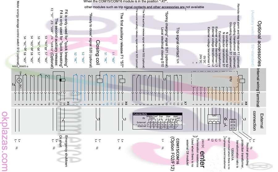
The distribution and connection circuit diagram of Siemens circuit breaker 3WL terminal is as follows:
The total circuit schematic diagram of Siemens circuit breaker 3WL is as follows:
(3WL1. ..–.....–4GN4–Z C11+ C22+K07) manual/electric energy storage operating mechanism, with electrical closing button (optional C11), close ready signal switch (optional C22), LSING overcurrent release, "UVR" undervoltage release (optional F3), "ST" shunt release (F1), trip signal switch (K07), auxiliary switch 4NO+4NC.
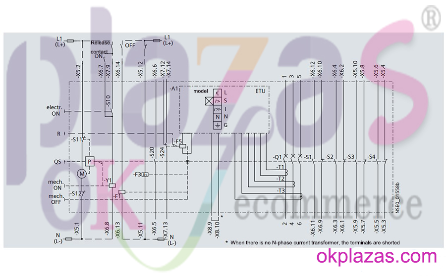
Note:
-A1: Electronic trip unit ETU;
-S1/-S2: The first auxiliary circuit wiring terminal (2NO+2NC);
-S3/-S4: The second auxiliary circuit terminal (2NO+2NC);
-S7 (optional) 2nd auxiliary circuit wiring terminal, S3 and S7 have the same terminal distribution/installation space, if there is no S3, S7 (2NO) can be used;
-S8 (optional) 2nd auxiliary circuit wiring terminal, S4 and S8 have the same terminal distribution/installation space. If S4 is not available, S8 (2NO) can be used
3WL1...-.....-...2 (2NO+2NC) S1+S2,
3WL1...-.....-...4 (4NO+4NC) S1+S2+S3+S4,
3WL1...-.....-...7 (6NO+2NC) S1+S2+S7+S8,
3WL1...-.....-...8 (5NO+3NC) S1+S2+S3+S8;
-S10 electrical closing button;
-S11 internal motor energy storage limit contact;
-S12 motor power switch (control whether to automatically store energy);
-S20 close ready signal switch;
-S24 trip signal switch;
-F1 first auxiliary release, shunt release;
-F3 second auxiliary release, undervoltage release;
-F5 trip coil;
-M "energy storage" motor;
-P energy storage institution;
-QS energy storage pole;
-Q1 main contact;
-T1/-T2/-T3 current transformer;
-X5/-X6/-X7/-X8 terminal group;
-Y1 closing coil;
-R trip indicator and reset button;
-X8.9/-X8.10 connection option: external neutral transformer.
The schematic diagram of Siemens circuit breaker 3WL functional connection circuit is as follows:
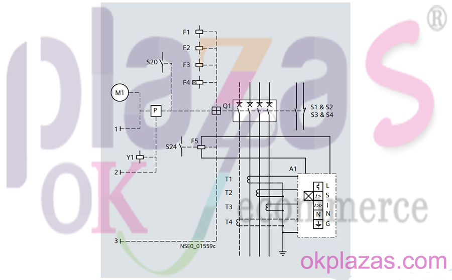
The above is the schematic diagram of Siemens air circuit breaker 3WL interlock and connection circuit, I hope it can help everyone.
-
The principle and application field of Autonics panel products (handling)
 June 12, 2021
 -
New product launch SRH1 series single-phase SSR with integrated heat sink
 June 12, 2021
 -
New product launch SRH1 series single-phase SSR with integrated heat sink
 June 12, 2021
 -
Otto protection grade IP69K new product launched Ø18mm cylindrical (SUS316L housing) photoelectric sensor BRQT series
 June 12, 2021
 -
Autonics adds shading motion mode sensor
 June 12, 2021