Siemens air circuit breaker 3WT wiring diagram and glossary
Siemens air circuit breaker 3WT wiring diagram and glossary
Overview of Siemens Air Circuit Breaker 3WT
The 3WT series of Siemens circuit breakers have a total of 500V and 690V rated voltages, and its current coverage is between 400A and 4000 (3800)A. The circuit breaker can be installed in a fixed or withdrawable type, and its breaking capacity is up to 66KA, which is usually suitable for use in a 2500KVA capacity transformer system. Siemens air circuit breaker 3WT full range of accessories are universal, which can effectively reduce the cost of spare parts. The powerful electronic release design meets various protection requirements. All electronic trip units are equipped with standard LCD display, with Chinese and English menus, and international and standardized production processes ensure that the quality of the products reaches a higher level.

Siemens air circuit breaker 3WT wiring diagram (general electrical schematic diagram)
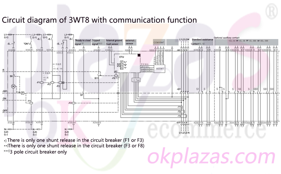
Note: The parameter description.
1. A1 electronic overcurrent release; 2. S1/S2 first auxiliary contact group;
3. S3/S4 second auxiliary contact group; 4. S5/S6 second auxiliary contact group;
5. S5/S60 second auxiliary contact group; 6. S60/S61 second auxiliary contact group;
7. S7 close ready signal contact; 8. S11 trip indication signal;
9. ON mechanical closing; 10. OFF mechanical closing;
11. F1 shunt release or electrical closing lock; 12. F2 shunt release;
13. F3 undervoltage release; 14. F8 undervoltage release with delay;
15. F5 circuit breaker trip electromagnetic coil; 16. M1 is a motor that stores energy for the energy storage spring mechanism;
17. P energy storage spring mechanism; 18. R overcurrent trip display and reset button;
19. Q01 spring energy storage handle of spring energy storage mechanism; 20. Q1 main contact;
21, T1/T2/T3 current transformer; 22, X100/X200/X300/X400 terminal block;
23. Y1 closing coil; 24. BSSWT circuit breaker status sensor, BSSWT;
25, V-Tap; 26, COM16WT communication module.
Electrical schematic diagram of Siemens air circuit breaker 3WT undervoltage release with delay
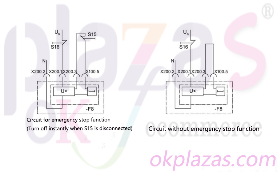
Note: S15 = external instantaneous shutdown, S16 = external delayed shutdown.
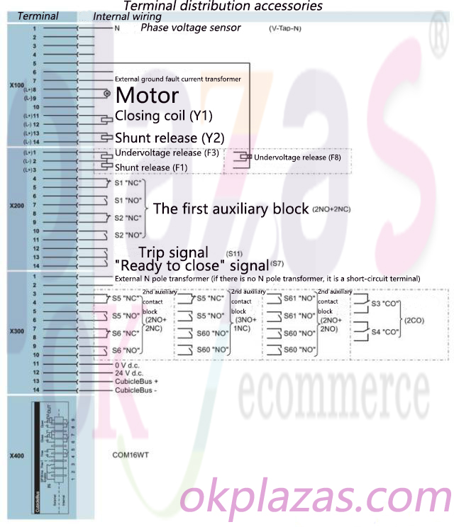
Siemens air circuit breaker 3WT terminal diagram
The following overview diagram shows the parts of the internal equipment and contact blocks that need to be connected accordingly, that is, the following diagram is a complete Siemens circuit breaker auxiliary wiring diagram.
Siemens air circuit breaker 3WT wiring diagram and glossary four
Siemens Air Circuit Breaker 3WT Glossary
◆BSSWT: 3WT Siemens circuit breaker status sensor, used to collect circuit breaker status information through signal switches and transmit these data to CubicleBUS.
◆COM16WT: 3WT communication module.
◆Powerconfig: software for debugging and service. For circuit breakers with communication function, powerconfig is used as a shared debugging and maintenance tool. The tool provides a standardized interface and a unified operator control concept for the operations to be performed, such as parameter setting, operation, monitoring, and diagnosis.
◆Safety baffle: The safety baffle is a molded plastic plate, which is used to cover the conductive main current path in the guide frame (to avoid the risk of electric shock). If the Siemens circuit breaker enters the open position, the safety flap will move above the unsealed contact gap.
◆Safe opening: This additional function can prevent the circuit breaker from closing and meet the isolation conditions of the OFF position in IEC60947-2: "Mechanical opening-the button is pressed, the main contact is opened, and the handle of the withdrawable circuit breaker has been moved in. Unload and meet different interlock conditions.
◆Rack drive guide: used to adjust the circuit breaker in the guide frame.
◆Energy storage spring mechanism: a unit with a spring energy storage device (mechanical energy), the spring is tensioned by a transmission handle or an electric operating mechanism, and is kept in tension by a latch. When the latch is released, the stored energy will be directed to the switch contacts and the Siemens air circuit breaker will be closed.
◆Spring energy storage rod: Energy storage spring mechanism is stored through a series of reciprocating motions (operating latch handle 5 times).
◆Motor operating mechanism: After applying voltage to the auxiliary power connection, the gear motor will automatically charge the energy storage spring mechanism. After each closing operation, the stored energy spring mechanism will automatically charge for the next closing operation.
◆Electrical connection interlock: This function is used to electrically interlock two or more circuit breakers (connection lockout), which can prevent the circuit breaker from being switched on by a continuous signal.
◆Rated current coding: The rated current coding is carried out in the factory, which means that each circuit breaker can only be used in the guide frame with the same rated current.
◆Shunt release (F1, F2): used to remotely disconnect the circuit breaker and prevent it from closing.
◆Auxiliary release: Undervoltage release and shunt release can be used.
◆ Closing coil: the energy in the electronic closing spring energy storage device.
◆Transducer: Generate the internal energy (power supply) of the overcurrent release.
◆Reed contacts: These contacts connect the main terminal of the Siemens circuit breaker with the main terminal of the guide frame.
◆Mechanical interlocking: This function supports mechanical interlocking of different types of circuit breakers.
◆Mechanical re-closing interlock: After over-current tripping, the circuit breaker will be locked to prevent re-closing until the mechanical re-closing locking function is manually reset.
◆Switch position signal switch: Control this auxiliary contact according to the switch state of the circuit breaker.
◆Undervoltage release (instantaneous/short-time delay): used to remotely disconnect and interlock the circuit breaker, and can connect the circuit breaker (according to EN60204-1/DIN VDE 0113 Part 1) with a separate Used in conjunction with the emergency stop equipment. A short voltage disturbance (for instantaneous undervoltage release, td<80 ms; for short-time delay undervoltage release, td<200 ms) shall not cause the circuit breaker to open.
◆Undervoltage release (delayed): used to remotely disconnect and interlock the circuit breaker. Voltage disturbance should not cause the circuit breaker to open.
◆Using tools: For buttons located under the cover and accessible through holes (diameter 6.35 mm), only suitable rods can be used to operate them.
◆Manual connector coding: Manual connector can be coded to avoid wrong connection of auxiliary wire connector.
◆Trip signal switch: Get group signals about overload, short circuit and ground fault trip through micro switch.
◆Position signal switch: used to remotely display the position of the circuit breaker in the guide frame.
◆Position indicator: Indicate the specific status position (disconnected/tested/run) of the Siemens circuit breaker 3WT in the guide frame.
The above is the Siemens air circuit breaker 3WT wiring diagram and glossary, I hope to help everyone. You can log in to the okplazas.com motor mall to view Siemens related product information, welcome to e-mail: [email protected] for consultation, and you can also contact WeChat customer service online at+86- 13689242098 for product consultation
-
The principle and application field of Autonics panel products (handling)
 June 12, 2021
 -
New product launch SRH1 series single-phase SSR with integrated heat sink
 June 12, 2021
 -
New product launch SRH1 series single-phase SSR with integrated heat sink
 June 12, 2021
 -
Otto protection grade IP69K new product launched Ø18mm cylindrical (SUS316L housing) photoelectric sensor BRQT series
 June 12, 2021
 -
Autonics adds shading motion mode sensor
 June 12, 2021