Siemens soft starter 3RW44 typical circuit diagram
Siemens soft starter 3RW44 typical circuit diagram
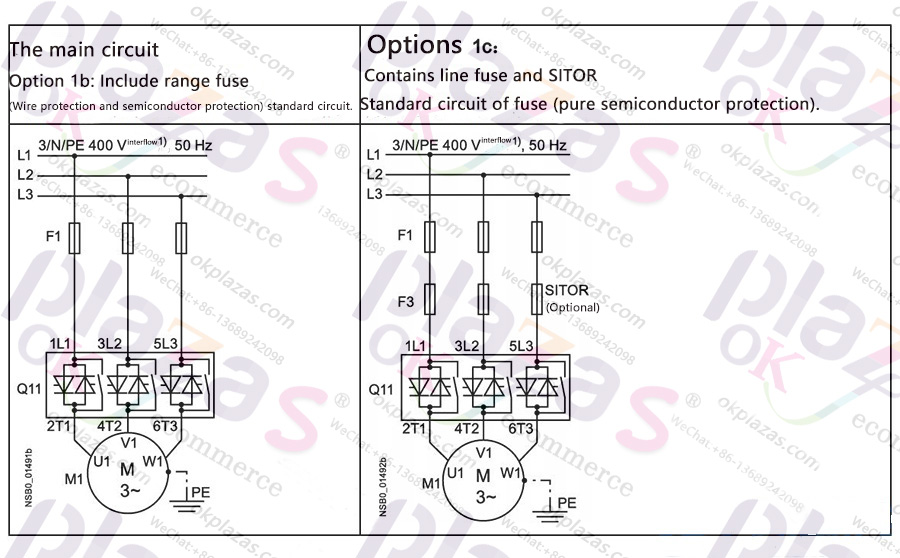
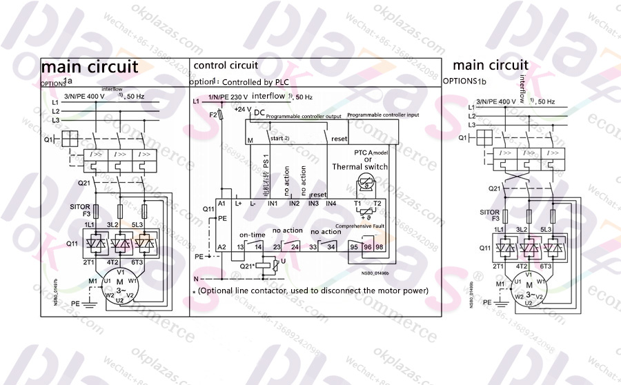
Connection example of main circuit and control circuit ◆Siemens soft starter 3RW44 adopts standard circuit and can be controlled by buttons. The specific circuit diagram is as follows.

◆The spare feeder configuration in the standard circuit, the specific circuit diagram is as follows.
◆Using standard circuit including line contactor and can be controlled by PLC, the specific circuit diagram is as follows.
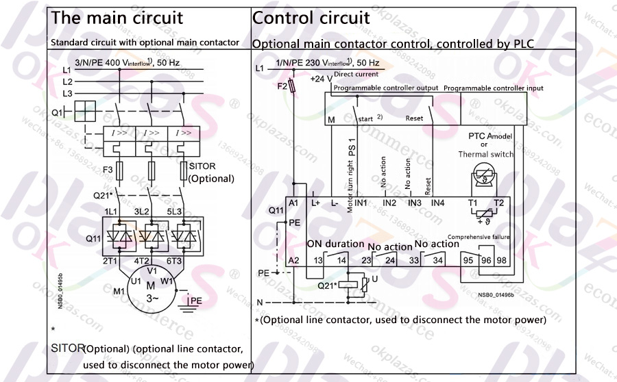
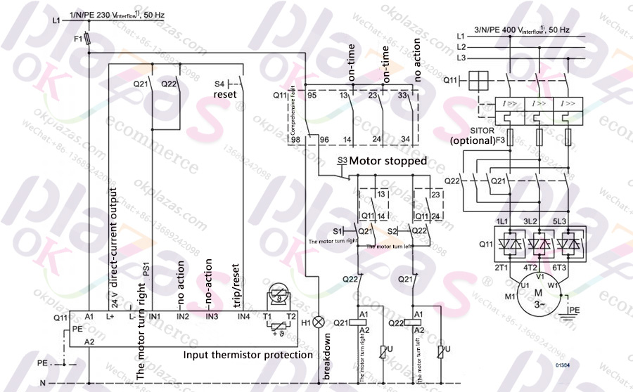
Note: Restart dangerous When a group fault occurs, the start command must be reset (for example, issued by the PLC), because if the start command is still valid after the reset command is issued, the motor will automatically restart again. This is especially suitable for motor protection trips, but for safety reasons, it is recommended to integrate group fault outputs (terminals 95 and 96) in the controller. ◆Siemens soft starter 3RW44 with standard circuit and DC brake stop function is used for equipment types from 3RW44 22 to 3RW44 25. The specific circuit diagram is as follows.
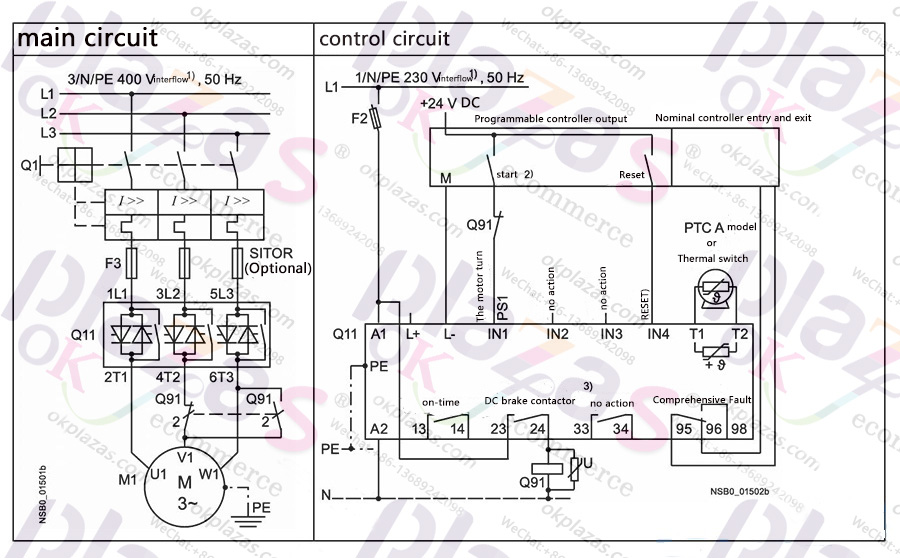
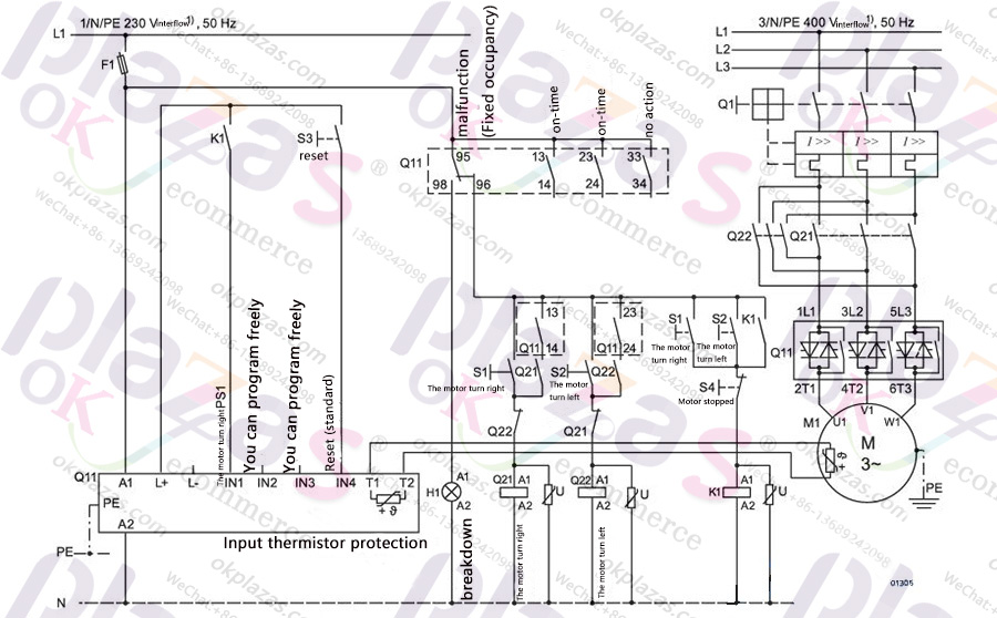
Note: Restart dangerous The starting command must be reset before issuing the reset command (for example, issued by PLC), because if the starting command is still valid, the motor will automatically restart again after the reset command is issued. This is especially true when the motor protection device trips. For safety reasons, it is recommended to integrate the group fault output (terminals 95 and 96) in the controller. If the soft starter "combined braking" stop function is selected, no braking contactor is required. If the "DC braking" function is selected, an additional braking contactor is required. For related types, please refer to the feeder component layout (standard circuit). For applications with large centrifugal mass (J load>J motor), it is recommended to use the "DC braking" function. Output 2 must be set to "DC braking contactor". ◆For Siemens soft starters 3RW44 26 to 3RW44 66 types, 3RW44 adopts standard circuit and DC braking stop function. The specific circuit diagram is shown below.
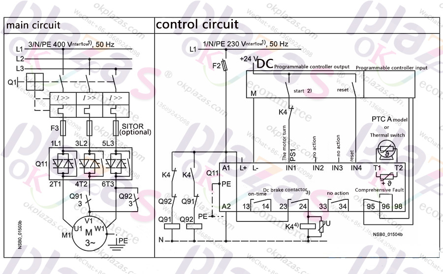
Note: Restart dangerous The starting command must be reset before issuing the reset command (for example, issued by PLC), because if the starting command is still valid, the motor will automatically restart again after the reset command is issued. This is especially true when the motor protection device trips. For safety reasons, it is recommended to integrate the group fault output (terminals 95 and 96) in the controller. If the soft starter "combined braking" stop function is selected, the brake contactor is not required. If the "DC braking" function is selected, a braking contactor is also required. For related types, please refer to the feeder component layout (standard circuit). For applications with large centrifugal mass (J load>J motor), it is recommended to use the "DC braking" function. Output 2 must be set to "DC braking contactor". Auxiliary relay K4, for example: LZS: RT4A4T30 (230V AC rated control power supply); LZS: RT4A4S15 (115 V AC rated control power supply). ◆The circuit diagram of the change of rotation direction in the inner delta and inner delta circuits used in the Siemens soft starter is shown below.
Description: 1. Please follow the wiring recommendations for the inner delta circuit given on the main circuit side. Incorrect connection will cause malfunctions. 2. Restart danger: the starting command must be reset before issuing the reset command (for example, sent by PLC), because if the starting command is still valid, the motor will automatically restart again after the reset command is issued. This is especially true when the motor protection device trips. For safety reasons, it is recommended to integrate the group fault output (terminals 95 and 96) in the controller. ◆Siemens soft starter 3RW44 adopts standard circuit, and its controller is like a contactor. The specific circuit diagram is shown below.
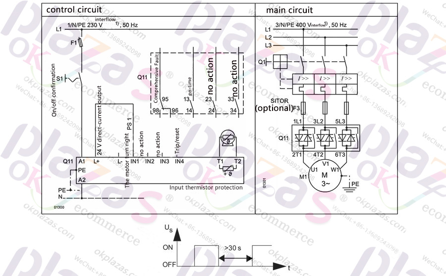
Description:
1. For this circuit type, after the start command is issued, the motor will start after a delay of up to 5s. This is because there is an internal running time of the soft starter and only the coast stop method is supported.
2. After cutting off the control power supply and before restarting, let the equipment cool down for at least 30s, because this will affect the effectiveness of the soft starter's self-protection function. If the switching frequency is high, this switching method is not recommended, because the fan of the device can no longer perform cooling operation after the soft starter is turned off, so the switching frequency given in the technical parameters will be less.
◆The soft starter 3RW44 with standard circuit, with soft start/stop function, and additional low-speed crawl function in both directions of rotation, only one parameter group, the specific circuit diagram is shown below.
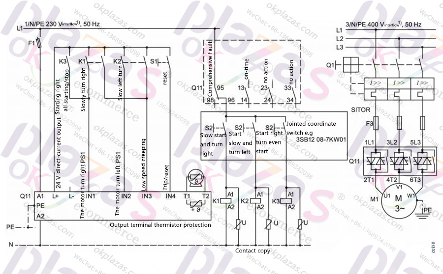
Description: 1. Parameter allocation sets the control input function to: IN1: Motor forward PS1; IN2: Motor reverse PS1; IN3: Slow mode IN4: Trip/reset (factory default setting); The slow speed parameter in parameter group 1 must be set. The forward rotation of the motor indicates rotation along the line phase direction, and the reverse rotation of the motor indicates the reverse direction rotation along the line phase. 2. The slow speed function is not suitable for continuous operation. When running continuously at a slow speed, the motor will generate severe heat and exceed the allowable range. 3. Restart danger: The start command must be reset before the reset command is issued, because if the start command is still valid after the reset command is issued, the motor will try to restart automatically again. This is especially true when the motor protection device trips. K1, K2, K3=relays used for contact multiplication, such as 230V AC operation: 3RS 1800-1BP00. ◆By switching to local manual operation mode and using @PROFIBUS to achieve control (for example, in the control cabinet), the specific circuit diagram is shown below.
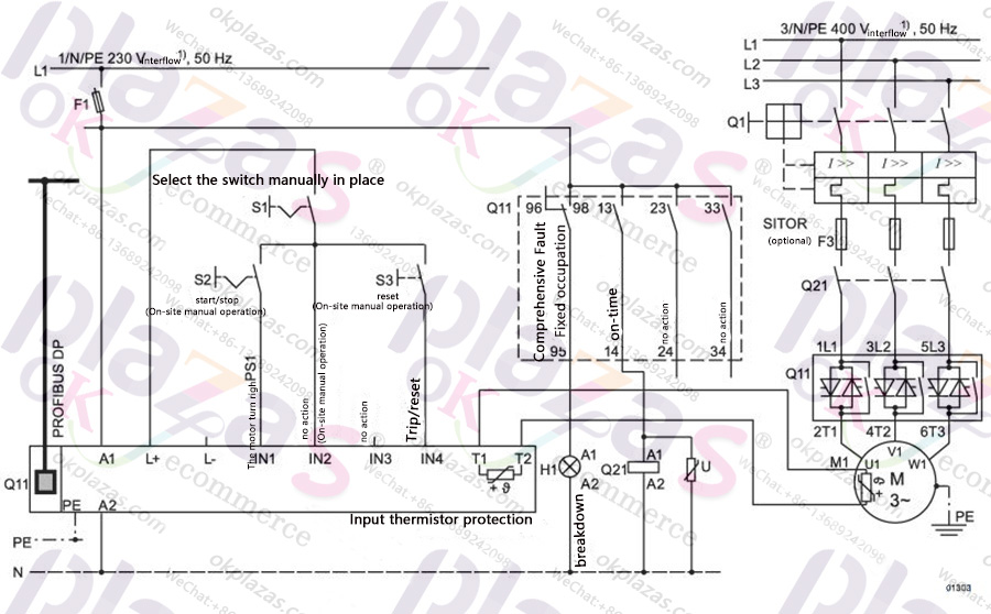
◆Siemens soft starter 3RW44 adopts standard circuit, realizes reversible operation through main contactor, with a parameter group, without soft stop function, the specific circuit diagram is shown below.
Note: The "Coasting down" coasting method must be set on the soft starter.
◆Reversible operation is realized through soft stop. The specific circuit diagram is shown below.
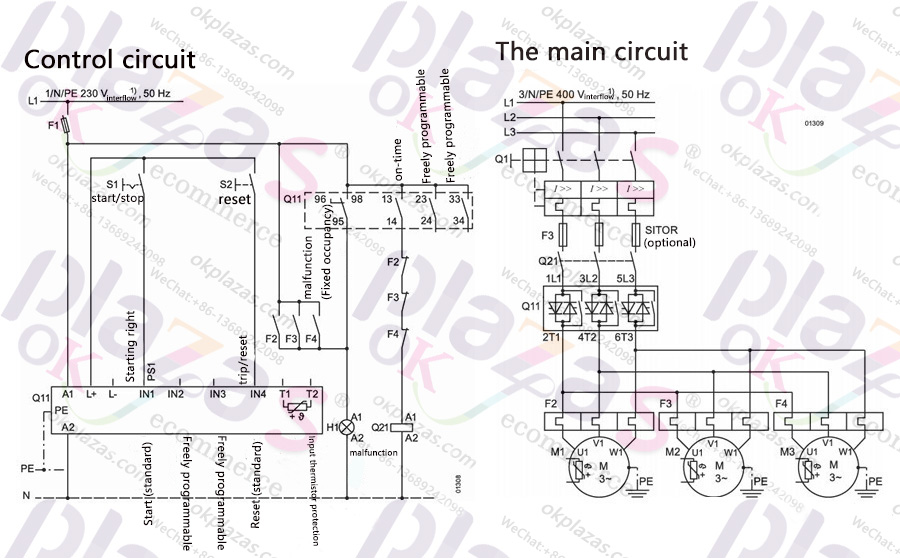
◆The parallel start control circuit and main circuit diagram of 3 motors are shown below.
◆Use 3 parameter groups to realize the soft starter of serial start. The specific circuit diagram is shown below.
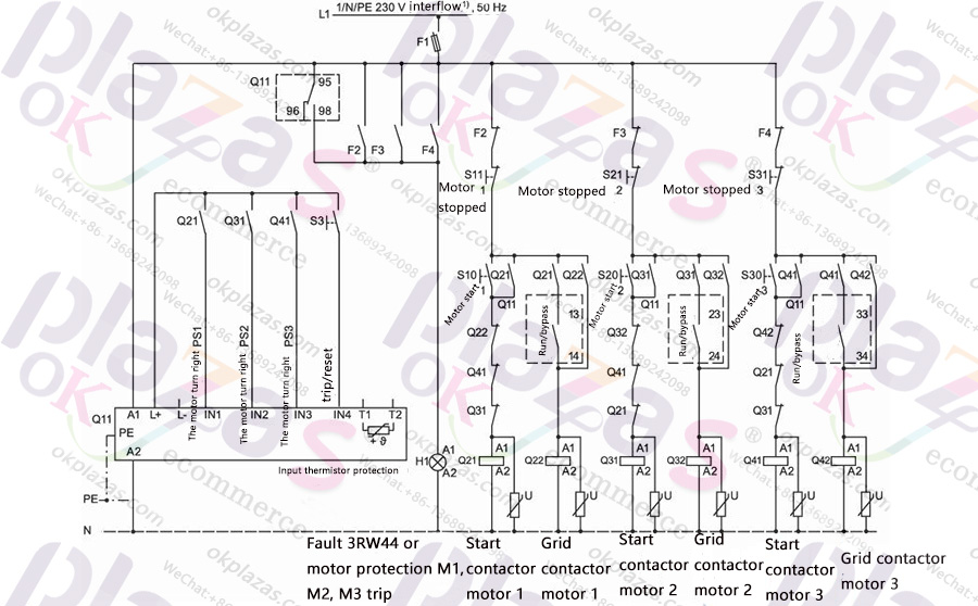
Description:
1. The "Coasting down" coasting method must be set on the 3RW44.
2. If the operation sequence is increased, the power of 3RW44 should be increased to at least one level higher than the maximum power of the connected motor.
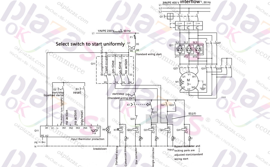
◆Soft starter with star-delta starter used for emergency start (3RW44 with standard circuit). The specific circuit diagram is shown below.
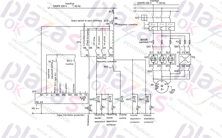
◆The specific circuit diagram of the soft starter and inverter on the same motor is shown below.
The above is a complete list of typical circuit diagrams of Siemens soft starter 3RW44, I hope to help you.okplazas.com is a professional sales agent for Siemens products. Welcome to email: okplazas.com for consultation. You can also contact WeChat customer service +86-13689242098 online for product consultation!
-
The principle and application field of Autonics panel products (handling)
 June 12, 2021
 -
New product launch SRH1 series single-phase SSR with integrated heat sink
 June 12, 2021
 -
New product launch SRH1 series single-phase SSR with integrated heat sink
 June 12, 2021
 -
Otto protection grade IP69K new product launched Ø18mm cylindrical (SUS316L housing) photoelectric sensor BRQT series
 June 12, 2021
 -
Autonics adds shading motion mode sensor
 June 12, 2021