Siemens soft starter 3RW55 installation, disassembly and wiring diagram
Siemens soft starter 3RW55 installation, disassembly and wiring diagram
Siemens soft starter 3RW55 installation, disassembly and wiring diagram
Siemens soft starter 3RW55 installation
◆Install 3RW55 soft starter on the horizontal surface
Claim:
1. Pay attention to the installation location, minimum clearance and environmental conditions mentioned in the data sheet.
2. A horizontal surface, such as a sufficiently strong mounting plate.
3, 4 correctly drilled holes.
4. Four screws with appropriate size and standard threads can be inserted into the selected mounting plate or wall. If the screw head is smaller than the specified diameter, use the included four washers.
5. Screwdriver (depending on the screw drive).
●The operation steps for installing Siemens soft starter 3RW55 size 1 to 4 are shown in the figure below.
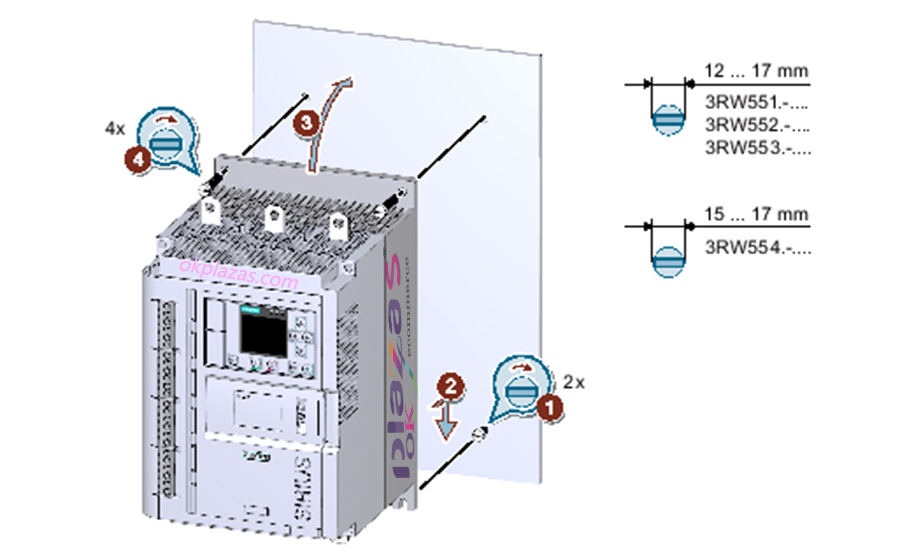
First screw the two screws below into the mounting plate①. Make sure that the two screws protrude at least 1.5 cm (for size 4, at least 2 cm), and then place the 3RW55 soft starter on the bottom two screws ② from above. Finally, tilt the 3RW55 soft starter up so that it is close to the horizontal surface of the mounting plate ③, and tighten all 4 screws ④.
●The operation steps for installing Siemens soft starter 3RW55 size 5 are shown in the figure below.
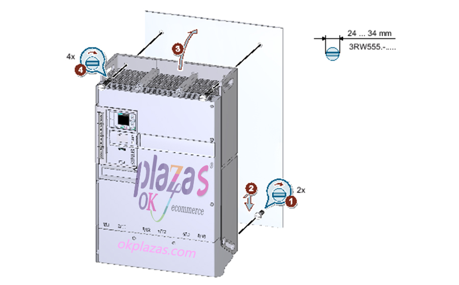
First screw the lower 2 screws into the mounting plate①, make sure that the two screws protrude at least 1.5 cm (for size 4, at least 2 cm), and then use the included handle to place the Siemens 3RW55 soft starter from above to the lower 2 On the screws ②. Finally, tilt the 3RW55 soft starter up so that it is close to the horizontal surface of the mounting plate ③, and tighten all 4 screws ④.
●Installation steps with lifting device:
Screw the lower two screws into the mounting plate ①, making sure that both screws protrude at least 2 cm. Use the 4 hooks of the lifting device to hook the holes provided on the 3RW55 soft starter. Place the 3RW55 soft starter from above on the 2 screws ② below. Tilt the 3RW55 soft starter upward so that it is close to the horizontal surface of the mounting plate ③, and tighten all 4 screws ④.
◆Install the fan cover
Claim:
1. Screwdriver T20.
2. A fan cover of appropriate size.
●The specific operation steps are shown in the figure below.
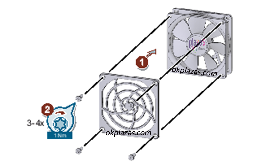
Place the fan cover on the fan ①, and then tighten the fan cover ②. Size 1 soft starter: 1 fan cover and 4 screws are required. Soft starters of sizes 2 and 3: 2 fan covers are required. According to the design, each fan cover requires 3 screws. Size 4 soft starter: 1 fan cover and 4 screws are required. The fan cover can enhance contact protection and prevent the fan from being blocked by foreign objects.
◆Install high-performance 3RW5 HMI in Siemens soft starter 3RW55
Claim:
1. High-performance 3RW5 HMI.
2. HMI connection cable 0.1m (accessory).
●The specific operation steps are shown in the figure below
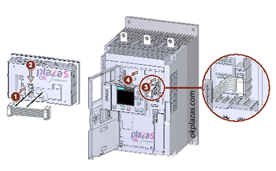
Pay attention to the coding on the plug and socket ①+③, and pay attention to the cable routing: ①to the right cable routing, ③to the left cable routing.
◆Replace the hinged cover of Siemens 3RW55 soft starter
Note: The HMI display is damaged.
Ensure that the HMI display is not damaged when replacing the rotating cover.
●The specific operation steps are shown in the figure below.
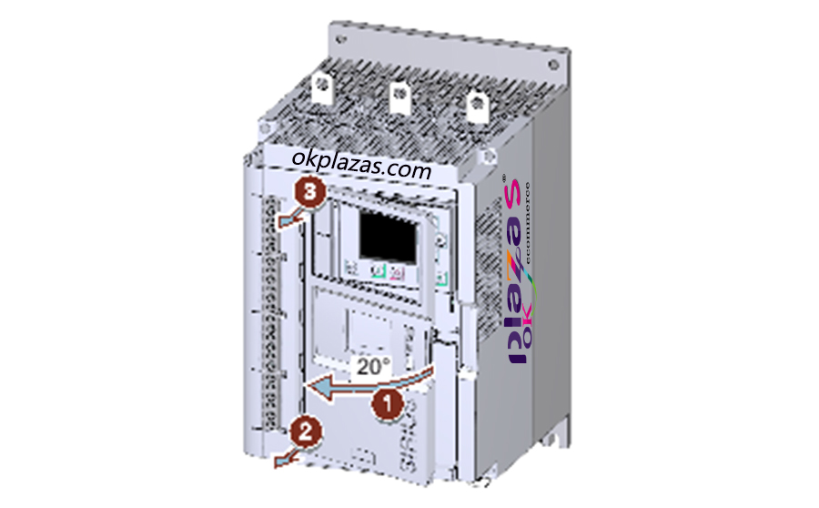
Open the rotary cover ① at an angle of about 20, and loosen the hinge perpendicular to the soft starter plane ②+③ from the bottom. Remove the cover from the 3RW55 soft starter and install the replacement rotary cover in the reverse order.
Siemens soft starter 3RW55 removed
◆Remove high-performance 3RW5 HMI
Claim:
1. Flat head screwdriver.
Note: If the sealing surface is damaged, make sure that the sealing surface is not damaged by a screwdriver.
●The specific operation steps are shown in the figure below.
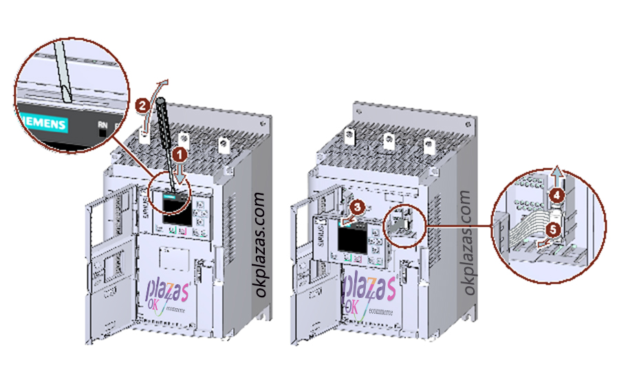
Use a flat-head screwdriver to remove the high-performance 3RW5 HMI in the reserved slot ①+②, and pull the high-performance 3RW5 HMI away from the Siemens 3RW55 soft starter ③ far enough to be able to reach the HMI connection cable. Loosen the fixing parts of the HMI connection cable ④, and pull out the HMI connection cable from the 3RW55 soft starter ⑤. Siemens soft starter 3RW55 wiring diagram
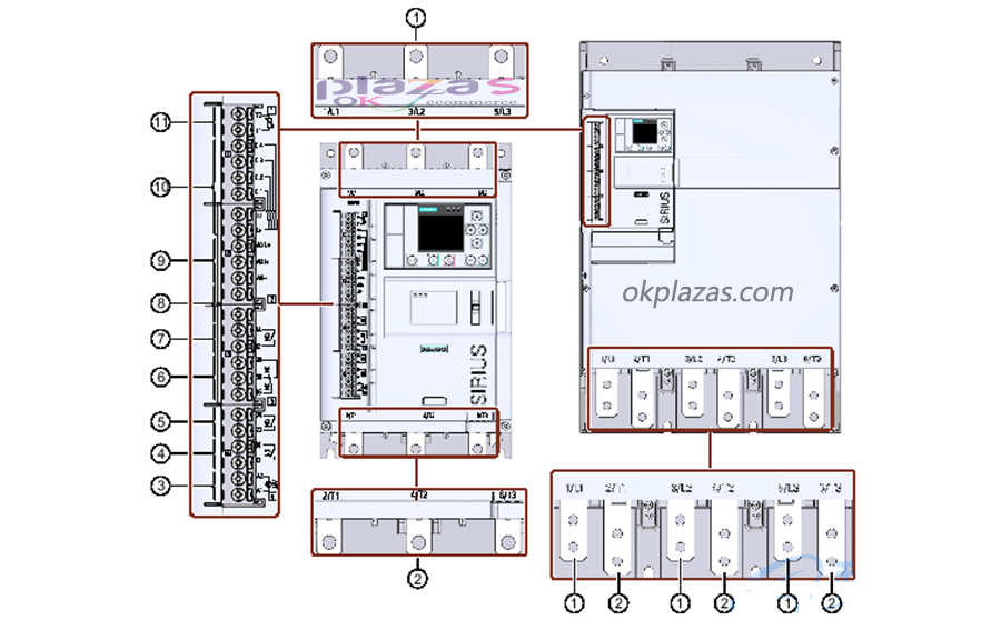
1. The main circuit is connected to the network 1/L1, 3/L2, 5/L3.
2. The main circuit is connected to the load (motor) 2/T1, 4/T2, 6/T3.
3. A1/A2: The power supply voltage of the control terminal.
4. Output 13, 14 (output 1): used to send out working status and faults (parameterizable).
5. Output 23, 24 (output 2): used to send out working status and faults (parameterizable).
6. Output 95, 96 and 98 (output 3): used to send out fault signals.
7. Output 43, 44 (output 4): used to send out working status and faults (parameterizable.)
8. Unallocated.
9. Analog output AQ-, AQ I+ and AQ U+: Connect measuring equipment to display motor current (optional).
AQ-/AQ U+: Used for measuring equipment whose output signal type is voltage and signal range is 0...10V.
AQ-/AQ I+: used for measuring equipment whose output signal type is current and signal range is 4...20mA.
10. Control inputs DI1, DI2, DI3, DI4, L+ and M.
11. Motor thermistor protection T1 and T2: connect temperature sensor (optional).
The above is the installation, disassembly and wiring diagram of Siemens soft starter 3RW55, I hope to help everyone. You can log on to the okplazas.com motor mall to view information about Siemens related products, welcome to email: [email protected] for consultation, and you can also contact WeChat customer service online at +86-13689242098 for product consultation!
-
The principle and application field of Autonics panel products (handling)
 June 12, 2021
 -
New product launch SRH1 series single-phase SSR with integrated heat sink
 June 12, 2021
 -
New product launch SRH1 series single-phase SSR with integrated heat sink
 June 12, 2021
 -
Otto protection grade IP69K new product launched Ø18mm cylindrical (SUS316L housing) photoelectric sensor BRQT series
 June 12, 2021
 -
Autonics adds shading motion mode sensor
 June 12, 2021