The control circuit analysis of photoelectric sensor
The control circuit analysis of photoelectric sensor
The photoelectric sensor is a device that can convert visible light signals into electrical signals. It can also be called a photoelectric device. It is mainly used in the fields of light-controlled switches, light-controlled lighting, and light-controlled alarms to control various visible lights.
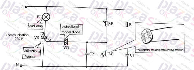
It can be seen from the figure below that the photoelectric sensor uses a photoresistor as a photoelectric element. The photoresistor is a light-sensitive element, and its resistance value changes with the intensity of the incident light.
When the ambient light is strong, the resistance value of the photoelectric sensor RG is small, so that the voltage division value between the adjustable resistor RP and the photoelectric sensor RG becomes lower, and the trigger voltage value of the bidirectional trigger diode VD cannot be reached, and the bidirectional trigger diode VD is cut off. , In turn, the bidirectional thyristor VS is also turned off, and the illumination lamp EL is turned off.
When the ambient light is weak, the resistance value of the photoelectric sensor RG becomes larger, so that the partial pressure value between the adjustable resistor RP and the photoelectric sensor RG becomes higher. As the light intensity gradually increases, the resistance value of the photoelectric sensor RG gradually changes When the voltage division value between the adjustable resistor kP and the photoelectric sensor RG reaches the trigger voltage of the two-way triggering of the two poles VD, the two-way trigger diode VD is turned on, and then the two-way trigger diode VS is also turned on, and the light is turned on. EL lights up.
-
The principle and application field of Autonics panel products (handling)
 June 12, 2021
 -
New product launch SRH1 series single-phase SSR with integrated heat sink
 June 12, 2021
 -
New product launch SRH1 series single-phase SSR with integrated heat sink
 June 12, 2021
 -
Otto protection grade IP69K new product launched Ø18mm cylindrical (SUS316L housing) photoelectric sensor BRQT series
 June 12, 2021
 -
Autonics adds shading motion mode sensor
 June 12, 2021