The function of the magnetic switch How to wire the magnetic switch
The function of the magnetic switch How to wire the magnetic switch
Keywords: photoelectric switch photoelectric switch manufacturer photoelectric switch model photoelectric switch price photoelectric switch wiring diagram photoelectric switch principle photoelectric switch type photoelectric switch application
Photoelectric switch:
The photoelectric switch is the abbreviation of the photoelectric proximity switch. It utilizes the shielding or reflection of the light beam by the detected object, and the circuit is connected by the synchronization loop to detect the presence or absence of the object. Objects are not limited to metal, all objects that can reflect light (or block light) can be detected. The photoelectric switch converts the input current into a light signal on the transmitter, and then the receiver detects the target object according to the intensity or presence of the received light. The common photoelectric switch smoke alarm in the security system is often used in the industry to count the number of movements of the robotic arm.
Photoelectric switch model:
The photoelectric switch is a kind of sensor, which converts the change of the intensity of light between the transmitting end and the receiving end into the change of current to achieve the purpose of detection. Since the output circuit and input circuit of the photoelectric switch are electrically isolated (ie, electrically insulated), it can be used in many occasions. A new generation of photoelectric switch devices manufactured using integrated circuit technology and SMT surface mounting technology has intelligent functions such as delay, widening, external synchronization, anti-interference, high reliability, stable working area and self-diagnosis. This novel photoelectric switch is an active photoelectric detection system electronic switch that adopts pulse modulation. The cold light sources it uses include infrared light, red light, green light and blue light, etc., which can be non-contact and rapid without damage. And control the state and action of various solids, liquids, transparent bodies, black bodies, soft bodies and smoke. It has the advantages of small size, multiple functions, long life, high accuracy, fast response speed, long detection distance and strong resistance to optical, electrical, and magnetic interference.
Photoelectric switch manufacturers:
Use optical elements to change the light beam in the middle of the propagation medium; use the light beam to reflect the object; make the light beam return instantly after a long distance. The photoelectric switch is composed of three parts: transmitter, receiver and detection circuit. The transmitter is aimed at the target to emit a beam, and the emitted beam generally comes from a light emitting diode (LED) and a laser diode. The beam is emitted continuously, or the pulse width is changed. The radiation intensity of the pulsed beam has been selected many times in the launch, and it runs towards the target without indirectly. The receiver is composed of a photodiode or phototransistor. In front of the receiver, optical components such as lens and aperture are installed. Behind it is the detection circuit, which can filter out the effective signal and apply the signal.
Working principle of photoelectric switch:
After the modulated pulse generated by the oscillation circuit passes through the reflection circuit, the light pulse is radiated from the light emitting tube GL. When the measured object enters the range of the light receiver, the reflected light pulse enters the photosensitive transistor DU. The photoelectric switch demodulates the optical pulse into an electric pulse signal in the receiving circuit, and then is amplified by the amplifier and synchronized gating and shaping, and then the interference is eliminated by digital integration or RC integration, and finally the driver is triggered by a delay (or no delay) Output photoelectric switch control signal. Photoelectric switches generally have good hysteresis characteristics, so even if the detected object shakes in a small range, it will not affect the output state of the driver, so that it can be kept in a stable working area. At the same time, the self-diagnostic system can also display the light receiving status and stable working area to monitor the work of the photoelectric switch at any time.
Types of photoelectric switches:
The amplifier separation type is to separate the amplifier and the sensor, and is made with a dedicated integrated circuit and a mixed installation process. Because the sensor has the characteristics of ultra-small and multi-variety, the amplifier has more functions. Therefore, this type adopts the terminal block connection method and can be used for both AC and DC power supplies. With on and off delay function, you can set the light and sound switch, can control 6 kinds of output states, and have two output modes of contact and level.
The built-in type of amplifier integrates the amplifier and the sensor. It is made by ASIC and surface mounting technology, and it works with DC power supply. Its response speed situation (there are two kinds of 0.1ms and 1ms), can detect small and high-speed moving objects. Changing the polarity of the power supply can switch between bright and dark movement, and can set a self-diagnostic stable work area indicator. Both voltage and current output modes can prevent mutual interference, which is very convenient in system installation.
The built-in power supply unit integrates the amplifier, sensor and power supply device, and is made with a dedicated integrated circuit and surface mount technology. It generally uses AC power and is suitable for replacing contact type limit switches at the production site, and can be directly used for strong current control circuits. You can also set self-diagnostic stable working area indicator lights by yourself. The output is equipped with SSR solid state relay or relay normally open and normally closed contacts, which can prevent mutual interference and can be installed tightly in the system.
Photoelectric switch price:
Strong light source: The photoelectric switch can generally work stably when the ambient illuminance is high. However, it should be avoided that the optical axis of the sensor faces strong light sources such as sunlight and incandescent lamps. When the angle between the optical axis of the sensor (receiver) and the strong light source cannot be changed, a light-shielding plate or a long light-shielding tube can be installed around the sensor.
Mutual interference: MGK series of new photoelectric switches usually have the function of automatically preventing mutual interference, so there is no need to worry about mutual interference. However, when several groups of HGK series through-beam infrared photoelectric switches are installed in parallel and close to each other, the adjacent groups and mutual interference should be prevented. The most effective way to prevent this kind of interference is to set the emitter and the receiver crosswise, and open the group distance when more than 2 groups. Different frequency models can also be used.
The effective way of HGK series reflective photoelectric switch to prevent mutual interference is to open the interval. And the farther the detection distance is, the larger the interval should be, and the specific interval should be determined according to the debugging situation. Of course, models with different operating frequencies can also be used.
Photoelectric switch wiring diagram:
The slot photoelectric switch is usually a standard U-shaped structure. The transmitter and receiver are located on both sides of the U-shaped groove and form an optical axis. When the detected object passes through the U-shaped groove and blocks the optical axis, the photoelectric switch The detected switch signal is generated. The slot photoelectric switch is safer and more suitable for detecting high-speed changes and distinguishing transparent and semi-transparent objects.
Optical fiber photoelectric switches use plastic or glass optical fiber sensors to guide light, so as to realize the detection of objects not in the vicinity. Generally, fiber optic sensors are divided into through-beam type and diffuse reflection type.
related suggestion:
Photoelectric switch
Pepperl+Fuchs
liquid level sensor
Ultrasonic sensor
Surge protector
Safety barrier
Photoelectric switch article:
Magnetic switch function
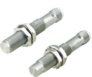
Magnetic proximity switch is a kind of proximity switch. Proximity switch is one of many types in the sensor family. It is made by using electromagnetic working principle and advanced technology. It is a kind of position sensor. It can transform the non-electricity or electromagnetic quantity into the desired electric signal through the change of the positional relationship between the sensor and the object, so as to achieve the purpose of control or measurement.
The magnetic proximity switch can reach the maximum detection distance with a small switch volume. It can detect magnetic objects (usually permanent magnets), and then generate trigger switch signal output. Since the magnetic field can pass many non-magnetic objects, this triggering process does not necessarily require the target object to be directly approached to the sensing surface of the magnetic proximity switch, but to transmit the magnetic field to a long distance through a magnetic conductor (such as iron). For example, the signal can pass The high temperature is transmitted to the magnetic proximity switch and the trigger action signal is generated.
Magnetic proximity switches are widely used in aviation, aerospace technology and industrial production. In daily life, such as hotels, restaurants, garages, automatic doors, automatic hot air blowers have applications. In terms of security and anti-theft, such important places as data files, accounting, finance, museums, and vaults are usually equipped with anti-theft devices composed of various proximity switches. In measurement technology, such as length and position measurement; in control technology, such as displacement, velocity, acceleration measurement and control, a large number of proximity switches are also used.
How to wire the magnetic switch
bk (black) black: generally the output line, the output is normally open.
bn (brown) brown: generally the power cord, connected to the positive pole of the power supply.
bu (blue) blue: generally the power cord, connected to the negative pole of the power supply.
wh (white) white: generally the output line, the output is normally closed.
npn: The black end is connected to the load, and the other end of the load is connected to the positive pole of the power supply.
pnp: The black end is connected to the load, and the other end of the load is connected to the negative pole of the power supply.
1. Proximity switches have the difference between two-wire and three-wire systems. Three-wire proximity switches are divided into NPN type and PNP type, and their wiring is different.
2. The wiring of the two-wire proximity switch is relatively simple. The proximity switch is connected to the power supply after being connected in series with the load.
3. Wiring of the three-wire proximity switch: the red (brown) wire is connected to the positive terminal of the power supply; the blue wire is connected to the 0V terminal of the power supply; the yellow (black) wire is the signal and should be connected to the load. The other end of the load is connected as follows: For NPN proximity switches, it should be connected to the positive end of the power supply; for PNP proximity switches, it should be connected to the 0V end of the power supply.
4. The load of the proximity switch can be a signal lamp, a relay coil or a digital input module of a programmable controller PLC.
5. Special attention should be paid to the type selection of the three-wire proximity switch connected to the PLC digital input module. PLC digital input modules can generally be divided into two categories: one type of public input terminal is the power supply 0V, the current flows from the input module (Japanese mode), at this time, the NPN type proximity switch must be selected; the other type of public input terminal It is the positive terminal of the power supply, and the current flows into the input module, that is, the well type input (European mode). At this time, the PNP type proximity switch must be selected. Don't choose the wrong one.
6.The two-wire proximity switch is limited by the working conditions. When it is turned on, the switch itself produces a certain voltage drop, and when it is turned off, there is a certain amount of residual current flowing. It should be considered when selecting it. Although the three-wire proximity switch has one more wire, it is not troubled by unfavorable factors such as residual current, and its work is more reliable. 7. Some manufacturers lead the "normally open" and "normally closed" signals of the proximity switch at the same time, or add other functions. In this case, please follow the product manual for specific wiring.
-
The principle and application field of Autonics panel products (handling)
 June 12, 2021
 -
New product launch SRH1 series single-phase SSR with integrated heat sink
 June 12, 2021
 -
New product launch SRH1 series single-phase SSR with integrated heat sink
 June 12, 2021
 -
Otto protection grade IP69K new product launched Ø18mm cylindrical (SUS316L housing) photoelectric sensor BRQT series
 June 12, 2021
 -
Autonics adds shading motion mode sensor
 June 12, 2021