The pros and cons of encoder technology
The pros and cons of encoder technology
In many applications, rotary encoders are the key components that make up the motion control feedback loop, including industrial automation equipment and process control, robotics, medical equipment, energy, aerospace, etc. As a device that converts mechanical motion into electrical signals, encoders can provide engineers with basic data such as position, speed, distance, and direction to optimize the performance of the entire system.
Optical, magnetic, and capacitive are the three main encoder technologies available to engineers. However, to determine which technology is best for the final application, there are some factors to consider. In order to help engineers choose the type, this article will outline the three encoder technologies of optical, magnetic and capacitive, and outline the trade-offs of various technologies.
Encoder technology overview
Optical encoder
For many years, optical encoders have been a popular choice in the motion control application market. It consists of an LED light source (usually an infrared light source) and a photodetector, which are located on both sides of the encoder code disc. The code disc is made of plastic or glass, on which a series of light-transmitting and opaque lines or grooves are arranged at intervals. When the code wheel rotates, the LED light path is blocked by lines or slots arranged at intervals on the code wheel, resulting in two typical square wave A and B orthogonal pulses, which can be used to determine the rotation and speed of the shaft.
Figure 1: Typical A and B quadrature pulses of an optical encoder, including index pulses (Image source: CUI Devices)
Although optical encoders are widely used, they still have several drawbacks. In dusty and dirty environments such as industrial applications, contaminants can accumulate on the code wheel, preventing the LED light from being transmitted to the optical sensor. The contaminated code disc may cause the square wave to be discontinuous or completely lost, which greatly affects the reliability and accuracy of the optical encoder. The LED has a limited lifespan and will eventually burn out, causing the encoder to malfunction. In addition, glass or plastic code discs are easily damaged by vibration or extreme temperature, which limits the scope of optical encoders in harsh environment applications; assembling them to motors is not only time-consuming, but also has a greater risk of contamination. Finally, if the resolution of the optical encoder is higher, it will consume more than 100 mA of current, further affecting its application in mobile devices or battery-powered devices.
Magnetic encoder
The structure of a magnetic encoder is similar to that of an optical encoder, but it uses a magnetic field instead of a light beam. The magnetic encoder uses a magnetic code disc instead of a slotted photoelectric code disc. The magnetic code disc has magnetic poles arranged at intervals and rotates on a row of Hall effect sensors or magnetoresistive sensors. Any rotation of the code wheel will make these sensors respond, and the generated signal will be transmitted to the signal conditioning front-end circuit to determine the position of the shaft. Compared with optical encoders, magnetic encoders have the advantage of being more durable, anti-vibration and anti-shock. Moreover, in the case of dust, dirt, oil stains and other contaminants, the performance of the optical encoder will be greatly reduced, but the magnetic encoder is not affected, so it is very suitable for harsh environment applications.
However, the electromagnetic interference generated by the motor (especially the stepper motor) will have a great impact on the magnetic encoder, and temperature changes will also cause position drift. In addition, the resolution and accuracy of magnetic encoders are relatively low, far inferior to optical and capacitive encoders in this respect.
Capacitive encoder
The capacitive encoder is mainly composed of three parts: a rotor, a fixed transmitter and a fixed receiver. Capacitive sensing uses striped or linear lines, one pole is located on the fixed element, and the other pole is located on the movable element to form a variable capacitor, and is configured as a pair of receiver/transmitter. The sine wave is etched on the rotor. As the motor shaft rotates, this pattern can produce a special but predictable signal. This signal is then converted by the encoder's onboard ASIC to calculate the position and direction of rotation of the shaft.

Figure 2: Comparison of encoder code discs (picture source: CUI Devices)
Advantages of capacitive encoder
The working principle of a capacitive encoder is the same as that of a digital vernier caliper, so the solution it provides overcomes many shortcomings of optical and magnetic encoders. Facts have proved that the capacitor-based technology adopted by CUI Devices' AMT encoder series has high reliability and high precision. Since there is no need for LEDs or line-of-sight, capacitive encoders can achieve the desired results even if they encounter environmental pollutants (such as dust, dirt, and oil stains) that can adversely affect the optical encoder. In addition, it is less susceptible to vibration and extremely high/low temperature than the glass code disc used in optical encoders. As mentioned earlier, because capacitive encoders do not have LED burnout, their service life is often longer than that of optical encoders. Therefore, the package size of the capacitive encoder is smaller, and the current consumption in the entire resolution range is smaller, only 6 to 18 mA, which makes it more suitable for battery-powered applications. In view of the robustness, accuracy and resolution of capacitive technology higher than that of magnetic encoders, the electromagnetic interference and electrical noise faced by the latter have little effect on it.
In addition, in terms of flexibility and programmability, the digital features of capacitive encoders can also bring key advantages. Because the resolution of an optical or magnetic encoder is determined by the encoder code disc, when other resolutions are needed, a new encoder must be used each time, so that the time and cost of the design and manufacturing process will increase. However, the capacitive encoder has a series of programmable resolutions, which saves designers the trouble of replacing the encoder every time a new resolution is needed. This not only reduces inventory, but also simplifies the fine-tuning of the PID control loop. And system optimization. When it comes to BLDC motor commutation, capacitive encoders allow digital alignment and index pulse settings, a task that can be repetitive and time-consuming for optical encoders. The built-in diagnostic function allows designers to further access system data to optimize the system or troubleshoot on-site.
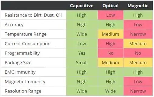
Figure 3: Comparison of key performance indicators of capacitive, optical and magnetic technologies (picture source: CUI Devices)
Trade-off options
In many motion control applications, temperature, vibration and environmental pollutants are important challenges that encoders must deal with. Facts have proved that capacitive encoders can overcome these challenges. Compared with optical or magnetic technology, it can provide designers with reliable, accurate and flexible solutions. In addition, capacitive encoders have added programmability and diagnostic functions. This digital feature makes it more suitable for modern Internet of Things (IoT) and Industrial Internet of Things (IIoT) applications.
-
The principle and application field of Autonics panel products (handling)
 June 12, 2021
 -
New product launch SRH1 series single-phase SSR with integrated heat sink
 June 12, 2021
 -
New product launch SRH1 series single-phase SSR with integrated heat sink
 June 12, 2021
 -
Otto protection grade IP69K new product launched Ø18mm cylindrical (SUS316L housing) photoelectric sensor BRQT series
 June 12, 2021
 -
Autonics adds shading motion mode sensor
 June 12, 2021