The structure, principle and application of incremental photoelectric encoder
The structure, principle and application of incremental photoelectric encoder
The structure, principle and application of incremental photoelectric encoder
Summary of content: The photoelectric encoder is a high-precision digital detection device. There is a knob that can be rotated left and right at the same time. It is widely used for menu selection and adjustment of vehicle electronic equipment. Mainly taking the Japan Alps EC11J miniature photoelectric encoder as an example, the structure and principle of the incremental photoelectric encoder are analyzed, and its application in the volume adjustment of car audio is explained. The encoder output control circuit is designed to distinguish the pulse direction and The counting software programming method further summarizes the main points of the program test to check the correctness of the program.
Keywords: photoelectric encoder; car audio system; software programming; program testing
The photoelectric encoder can convert a mechanical geometric displacement into an electronic signal (electronic pulse signal or data string) through the photoelectric principle. It is a digital detection device integrating light, machine and electricity. It has the advantages of high precision, simple structure, small size, reliable use, easy maintenance, and high cost performance.
Generally speaking, depending on the way the photoelectric encoder generates pulses, it can be divided into three categories: incremental, absolute, and composite. The incremental rotary photoelectric encoder is easy to be made into a fully enclosed type, which is easy to realize miniaturization. It looks like a potentiometer, because there is a knob that can be turned left and right and can be pressed at the same time. Many devices (such as displays, oscilloscopes, etc.) use it as a human-computer interaction interface. It is widely used in in-vehicle electronic equipment for display menu selection, volume control and adjustment of car audio, and control and adjustment of car air conditioning. The author mainly takes the Japan Alps EC11J miniature photoelectric encoder as an example, analyzes the structure and principle of the incremental rotary encoder, and further proposes how to use the software program to realize the direction and count of the output pulse during the car volume control adjustment process . Unless otherwise specified in the article, the mentioned encoders all refer to incremental rotary photoelectric encoders.
1 The structure and working principle of photoelectric encoder
1.1 The structure of the encoder
A typical incremental photoelectric encoder is mainly composed of mechanical system, data scanning system, and electrical system.
The mechanical system mainly plays the role of housing and rotation support.
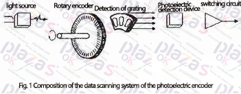
The data scanning system consists of a light source, a code disc, a detection grating, and a photoelectric detection device, as shown in Figure 1. The code disc is engraved with radial light-transmitting slits of equal pitch, and the adjacent two light-transmitting slits represent an incremental period; the detection grating is engraved with two groups of A and B corresponding to the code disc. Used to pass or block the light between the light source and the photoelectric detection device. Their pitch is equal to the pitch on the code disc, and the two sets of light-transmitting gaps are staggered by 1/4 pitch, so that the signals output by the photoelectric detection device are 90° out of phase. In most cases, the signal level obtained directly from the photoelectric detection device of the encoder is low, the waveform is irregular, and it cannot meet the requirements of control, signal processing and long-distance transmission. Therefore, the encoder must also amplify and reshape this signal.
The electrical system part mainly includes protection circuit, amplifying circuit, anti-interference circuit, data conversion output, etc. 1.2 The working principle of the encoder When the code wheel rotates with the rotating shaft, the detection grating does not move, the light passes through the gap between the code disk and the detection grating and irradiates the photoelectric detection device, and the photoelectric detection device will output two sets of phase difference 90° Pulse signal. Figure 2 (a) is a typical circuit for the generation of the A/B phase pulse signal of the photoelectric encoder. The dashed frame is a gap. If the detection grating blocks the light from the light source to the phototransistor, the triode will be cut off. At this time, the A/B phase input is at a logic high level due to the influence of the pull-up circuit, as shown in Figure 2(b). On the contrary, the phototransistor is irradiated by the light-emitting diode and is in a saturated state (that is, conductive). At this time, the A/B phase is connected to ground and presents a logic low level. Therefore, when the code wheel rotates, it will generate A/B phase pulses as shown in Figure 3.
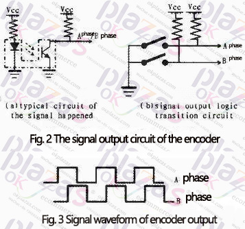
In order to achieve the purpose of accurate rotation in use, the designer divides the encoder's code wheel into several equal parts and installs springs so that the encoder must rotate to an integer multiple of the minimum scale as long as it rotates. When the encoder rotates forward, phase A is 90° ahead of phase B, and when it rotates backward, phase A is 90° behind phase B. In this way, the rotation amount of the encoder can be determined by the rotating scale, and the rotation direction of the encoder can be known through the phase relationship of the A/B phase pulse.
2 The application of encoder in car audio system
2.1 Application of encoder
The EC11J series encoder is a small, high-precision sliding encoder for vehicles produced by Alps Electric Co., Ltd. in Japan. Mainly used for car navigator, audio volume adjustment, air conditioning temperature adjustment knob and menu selection, etc.
In modern car audio systems, since the power supply of on-board electronics is the battery that comes with the car, the power supply is often affected by external interference (such as bumps on the road, increased engine speed, etc.), causing voltage instability, even the position of the potentiometer If there is no change, the output voltage of the potentiometer will change due to the change of the battery voltage. This will cause the volume to change with the change of the battery voltage even if the volume is not adjusted. Therefore, the potentiometer whose output is an analog voltage signal is generally not used as Adjust the knob.
The encoder output is a stable and reliable digital signal, which can be controlled by the programmable control of the next-level equipment to achieve accurate volume adjustment and eliminate interference. When the encoder is used, it can rotate 360°, has a fast response speed, accurate measurement of the amount of rotation, small rotating sound, and at the same time it has a long life, no noise, simple circuit, which is unmatched by a potentiometer. Compared with potentiometers and other components, it is more conducive to volume adjustment, which requires continuous changes.
2.2 Encoder output control circuit program design
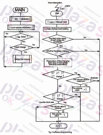
The direction and counting of the output pulse of the encoder can be realized by hardware circuit, and can also be realized by software method. The following mainly introduces the microcontroller programming control to realize the pulse direction and counting. This method adopts 1 ms regular query mode to read the A/B phase pulse status. In order to ensure the correctness of reading the A/B phase pulse status, three consistent debounces are required, and then according to the phase relationship of the encoder output waveform , Determine the rotation direction and amount of rotation of the encoder. The concrete software flow chart is shown as in Fig. 4.

2.3 Key points of program testing
An encoder is used as a volume adjustment knob in the car audio system, which has a small amount of rocking and a small virtual position of rotation. However, during the driving of the vehicle, the engine and other on-board electronic equipment may cause electromagnetic interference or other interference to the output waveform of the encoder, which requires the program to be able to identify the interference, and will not miscount and judge the direction. You can use a signal generator to generate pulses, simulate encoder output pulses, and connect them to the input port of the microcontroller to test the program from the following aspects.
1) Confirmation of positive and negative directions and increase or decrease
Input n-period positive pulses to the single-chip microcomputer, the waveform is shown in Figure 5, verify whether the program can correctly detect the positive direction and verify whether the increase or decrease amount increases by n. Similarly, verify the opposite direction.

2)Confirmation of single-phase disconnection error. When the encoder fails and the A-phase or B-phase is disconnected, the disconnected phase is always at logic high or logic low, and the other phase has a normally changing pulse waveform. Use the signal generator to simulate the abnormality of phase A or B of the encoder, which is always high or low. There are 4 situations in total as shown in Figure 6. Whether the test program can identify abnormalities and the count will not change.

When the car passes through the gravel road, strong micro-vibration and electromagnetic interference from other electronic equipment on the vehicle will affect the abnormal logic waveform of the encoder output as shown in Figure 7. After testing, it is confirmed that these micro-vibrations will not cause changes in program variable values.

3 concluding remarks
The photoelectric rotary encoder has comprehensive technical advantages such as good rotary controllability, accurate rotary positioning, small size, light weight, simple structure, and digital output. It is also equipped with accurate signal recognition of next-level programmable equipment such as single-chip microcomputers. , Has a strong anti-interference ability, and has been widely used in automotive electronic products.
With the rapid development of the automobile industry, the application of electronic technology has penetrated into almost all automobile systems. Various new types of photoelectric encoders using new principles and new technologies will continue to appear, and will develop in the direction of miniaturization, intelligence and integration to meet the needs of automotive safety, comfort, economy and entertainment.
-
The principle and application field of Autonics panel products (handling)
 June 12, 2021
 -
New product launch SRH1 series single-phase SSR with integrated heat sink
 June 12, 2021
 -
New product launch SRH1 series single-phase SSR with integrated heat sink
 June 12, 2021
 -
Otto protection grade IP69K new product launched Ø18mm cylindrical (SUS316L housing) photoelectric sensor BRQT series
 June 12, 2021
 -
Autonics adds shading motion mode sensor
 June 12, 2021