The working principle of encoder quadrature encoding
The working principle of encoder quadrature encoding
Quadrature encoder (also known as dual-channel incremental encoder), used to convert linear shifts into pulse signals. By monitoring the number of pulses and the relative phase of the two signals, the user can track the rotation position, rotation direction and speed. In addition, the third channel is called the index signal, which can be used to reset the position counter to determine the absolute position.
working principle:
The incremental encoder converts the encoder's steering into the timing and phase relationship of the A-phase and B-phase pulses through two internal photosensitive receiving tubes. The encoder also outputs a Z-phase pulse per revolution to represent the zero reference position.
As shown in Figure 3-1, points A and B correspond to two photosensitive receiving tubes, the distance between points A and B is S2, and the grating distance of the encoder is S0 and S1 respectively.
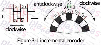
When the encoder rotates at a constant speed, the S0:S1:S2 ratio in the output waveform is the same as the actual encoder's S0:S1:S2. If the encoder performs variable-speed motion, it can be regarded as a combination of multiple motion cycles, then the S0:S1:S2 ratio of the output waveform of each motion cycle is still the same as the S0:S1:S2 of the actual encoder.
The output waveform shows that the timing of each motion cycle is
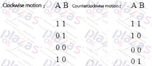
We save the current A and B output values and compare them with the next A and B output values to get the encoder movement direction. The angular velocity of the encoder movement is obtained by removing the time consumed by the angular position of the encoder movement.
If S0=S1, and S2=S0/2, the movement direction and displacement angle can be obtained in 1/4 of the movement cycle, otherwise it takes 1 movement cycle to get the movement direction and displacement angle.
In summary, we can judge the positive and negative rotation of the encoder by judging the phase relationship between the A phase and the B phase, and obtain the zero reference position through the Z phase pulse.
Some technical parameters of incremental encoders are as follows:
Resolution: The number of open or dark engraved lines provided by the encoder per revolution is called resolution, also called resolution division or directly called the number of lines. Generally, 5~10000 lines per revolution.
Signal output: There are sine wave (current or voltage), square wave (TTL/HTL) and many other forms of signal output. Among them, the form of TTL square wave is long-line differential signal (symmetrical A+, A-; B+, B-; Z+, Z-).
Signal connection: The pulse signal of the encoder is generally connected to the counter, PLC, and computer. There are single-phase connection (used for single-directional speed measurement and counting); AB two-phase connection (used for two-way speed measurement, counting and direction judgment); ABZ three-phase connection (used for position measurement with reference position correction); differential connection ( Used for long-distance transmission).
Incremental encoders are cheaper and easier than absolute encoders in angle measurement and angular velocity measurement. However, there are problems such as poor anti-interference ability, zero accumulated error, power-off memory for receiving equipment shutdown, and reference position for starting up. Generally used in speed measurement, rotation direction measurement, movement angle measurement, relative distance measurement, etc.
-
The principle and application field of Autonics panel products (handling)
 June 12, 2021
 -
New product launch SRH1 series single-phase SSR with integrated heat sink
 June 12, 2021
 -
New product launch SRH1 series single-phase SSR with integrated heat sink
 June 12, 2021
 -
Otto protection grade IP69K new product launched Ø18mm cylindrical (SUS316L housing) photoelectric sensor BRQT series
 June 12, 2021
 -
Autonics adds shading motion mode sensor
 June 12, 2021