The working principle of the encoder, analysis of the working principle of the photoelectric encoder
The working principle of the encoder, analysis of the working principle of the photoelectric encoder
The working principle of the encoder, analysis of the working principle of the photoelectric encoder
The working principle of the encoder, analysis of the working principle of the photoelectric encoder
How the encoder works
Absolute pulse encoder: APC
Incremental pulse encoder: SPC
Both are generally used in the detection elements of speed control or position control systems.
Rotary encoder is a device used to measure speed. It is divided into two types: single output and dual output. Technical parameters mainly include the number of pulses per revolution (dozens to thousands of them), and power supply voltage. Single output means that the output of the rotary encoder is a set of pulses, while the dual output rotary encoder outputs two sets of pulses with a phase difference of 90 degrees. The two sets of pulses can not only measure the speed, but also determine the direction of rotation.
The difference between incremental encoder and absolute encoder
If the encoder is divided into signal principle, there are incremental encoder and absolute encoder.
Incremental encoder (rotary type)

working principle:
A photoelectric code disc with an axis in the center, on which there are circular and dark engraved lines, is read by photoelectric transmitting and receiving devices, and four groups of sine wave signals are combined into A, B, C, D, each sine wave A phase difference of 90 degrees (360 degrees relative to a cycle), the C and D signals are reversed and superimposed on the A and B phases to enhance the stable signal; in addition, a Z-phase pulse is output every revolution to represent the zero reference Bit.
Since the phases A and B are 90 degrees apart, the encoder's forward and reverse rotation can be judged by comparing the phase A or the phase B. The zero reference position of the encoder can be obtained through the zero pulse.
The materials of the encoder code disc are glass, metal, plastic. The glass code disc is deposited on the glass with very thin scribe lines, which has good thermal stability and high precision. The metal code disc is directly engraved with through and impassable lines and is not fragile. However, due to the certain thickness of metal, the accuracy is limited, and its thermal stability is one order of magnitude worse than that of glass. Plastic code discs are economical, and their cost is low, but accuracy, thermal stability, and life are worse. .
Resolution—The number of open or dark engraved lines provided by the encoder per 360 degree rotation is called resolution, which is also called resolution division, or directly called the number of lines, generally 5 to 10,000 lines per revolution.
Signal output:
The signal output has sine wave (current or voltage), square wave (TTL, HTL), open collector (PNP, NPN), push-pull multiple forms, of which TTL is long-line differential drive (symmetrical A, A-; B, B -;Z,Z-), HTL is also called push-pull and push-pull output. The signal receiving device interface of the encoder should correspond to the encoder.
Signal connection—The pulse signal of the encoder is generally connected to the counter, PLC, and computer. The modules connected between the PLC and the computer are divided into low-speed modules and high-speed modules, and the switching frequency is low or high.
Such as single-phase connection, used for single direction counting and single direction speed measurement.
A.B two-phase connection, used for forward and reverse counting, judgment of forward and reverse and speed measurement.
A, B, Z three-phase connection, used for position measurement with reference position correction.
A, A-, B, B, B-, Z, Z-connections, due to the connection with symmetrical negative signals, the electromagnetic field contributed by the current to the cable is 0, the attenuation is the smallest, the anti-interference is the best, and it can be transmitted over a long distance.
For TTL encoders with symmetrical negative signal output, the signal transmission distance can reach 150 meters.
For HTL encoders with symmetrical negative signal output, the signal transmission distance can reach 300 meters.
Definition and function of encoder:
In digital systems, it is often necessary to transform a certain information (input) into a certain code (output). Arrange binary codes according to certain rules, such as 8421 codes, Gray codes, etc., so that each group of codes has a specific meaning (representing a certain number or control signal) is called a code. The logic circuit with encoding function is called encoder. The encoder has several inputs, and only one input signal is converted into a binary code at a certain time. If an encoder has N input terminals and n output terminals, the relationship between the output terminal and the input terminal should satisfy the relationship N≤2n. For example, 8-wire-3 wire encoder and 10-wire-4 wire encoder have 8 input, 3-bit binary code output and 10-input, 4-bit binary code output respectively.
1.4 line-2 line encoder
The working principle of the encoder with 4 inputs and 2 binary outputs is analyzed below. The function of 4-wire-2 wire encoder is shown in Table 5.2.1.
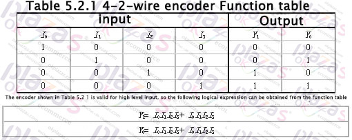
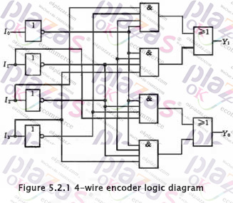
Draw the logic diagram according to the logic expression as shown in Figure 5.2.1. This logic circuit can realize the functions shown in Table 5.2.1, that is, when one of the inputs I0~I3 is 1, the output Y1Y0 is the corresponding code, for example, when I1 is 1, Y1Y0 is 01. There is one more issue here for readers' attention. When I0 is 1, I1~I3 are all 0 and I0~I3 are all 0, Y1Y0 are all 00, and these two situations must be distinguished in practice. This problem will be solved later. Of course, the encoder can also be designed to be active low.
2. Keyboard input 8421BCD code encoder:
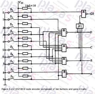
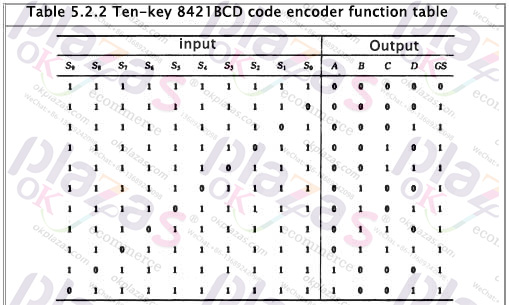
The keyboard input logic circuit of the computer is composed of an encoder. Figure 5.2.2 is an 8421 code encoder composed of ten buttons and gate circuits. Its functions are shown in Table 5.2.2, where S0~S9 represent ten buttons, that is, input keys corresponding to decimal numbers 0-9. They The corresponding output codes are just 8421BCD codes, and they are also used as logic variables. ABCD is the output code (A is the highest bit), and GS is the control enable flag.
Analyzing the function table and logic circuit, we can know that: ①The encoder is input low-level valid; ②When any key of S0~S9 is pressed, that is, when one of the input signals is at valid level, GS =1, it means there is signal input, and only when S0~S9 are all high level, GS=0, it means no signal input, the output code 0000 at this time is invalid code. This solves the problem of how to distinguish between the two cases where the output is all 0.
In summary, the encoder can be summarized as follows:
1. The number of input terminals of the encoder N (the number of information to be encoded) and the number of output terminals n (the number of bits of the resulting code) should satisfy the relationship N≤2n.
2. Each input terminal of the encoder represents a binary number, decimal number or other information symbol, and only one input signal is allowed at a time among the N input terminals (input low level is valid or input high level Valid), the output is the corresponding binary code or two-decimal code (BCD code).
3. Correct use of the control end of the encoder can be used to extend the function of the encoder.
1. The working principle of photoelectric encoder
The photoelectric encoder is a sensor that converts the mechanical geometric displacement on the output shaft into pulses or digital quantities through photoelectric conversion. This is the purpose
The most widely used sensor in the past, the photoelectric encoder is composed of a grating disc and a photoelectric detection device. The grating disc is divided equally on a circular plate of a certain diameter
Open several rectangular holes in the ground. Since the photoelectric code disc is coaxial with the motor, when the motor rotates, the grating disc and the motor rotate at the same speed.
The detection device composed of photodiodes and other electronic components detects and outputs several pulse signals. The schematic diagram of the principle is shown in Figure 1. By calculating the light per second
The number of output pulses of the electric encoder can reflect the current motor speed. In addition, in order to determine the direction of rotation, the encoder can also provide phase difference
Two pulse signals at 90o.
According to the detection principle, encoders can be divided into optical, magnetic, inductive and capacitive. According to its calibration method and signal output form, it can be divided into
There are three types: incremental, absolute and mixed.
(1) Incremental encoder
Incremental encoders directly use the principle of photoelectric conversion to output three sets of square wave pulses A, B and Z; the A and B pulses have a phase difference of 90o, which can
The direction of rotation is easily judged, and the Z-phase is one pulse per revolution, used for reference point positioning. Its advantages are simple structure and mechanical average
The service life can be more than tens of thousands of hours, the anti-interference ability is strong, the reliability is high, and it is suitable for long-distance transmission. The disadvantage is that the output shaft cannot rotate absolutely.
For location information.
(2) Absolute encoder
Absolute encoder is a sensor that directly outputs digital quantities. There are several concentric code tracks along the radial direction on its circular code disc. Each track is composed of light and
The opaque sectors are alternately formed, and the number of sectors of adjacent code channels is doubled. The number of code channels on the code disc is its binary code bit.
There is a light source on one side of the code disc, and a photosensitive element corresponding to each code track on the other side; when the code disc is in different positions, each photosensitive element
According to whether it is illuminated or not, the corresponding level signal is converted into a binary number. The feature of this kind of encoder is that it does not need a counter, and it is
The position can read a fixed digital code corresponding to the position. Obviously, the more code channels, the higher the resolution. For an N-bit
For encoders with binary resolution, the code disk must have N code channels. At present, there are 16-bit absolute encoder products in China.
The absolute encoder uses natural binary or cyclic binary (Grey code) method for photoelectric conversion. Absolute encoder and incremental
The difference of the encoder is the transparent and opaque line pattern on the disc. The absolute encoder can have several codes. According to the code on the read code disc
Code to detect the absolute position. The coding design can adopt binary code, cyclic code, two's complement code, etc. Its unique features are:
1. The absolute value of the angle coordinate can be read directly;
2. No cumulative error;
3. The position information will not be lost after the power is cut off. But the resolution is determined by the number of bits in the binary system, which means that the accuracy depends on the number of bits.
There are currently 10, 14 and so on.
(3) Hybrid absolute value encoder
Hybrid absolute encoder, it outputs two sets of information: one set of information is used to detect the magnetic pole position, with absolute information function; the other set is complete
Identical output information of incremental encoder.
The photoelectric encoder is an angle (angular velocity) detection device. It converts the angle input to the shaft into the corresponding
Electric pulse or digital quantity has the advantages of small size, high precision, reliable work, and digital interface. It is widely used in CNC machine tools and rotary tables
, Servo drives, robots, radars, military target determination and other devices and equipment that need to detect angles.
2. Application circuit of photoelectric encoder
(1) Application of EPC-755A photoelectric encoder
EPC-755A photoelectric encoder has good performance, strong anti-interference ability in angle measurement and displacement measurement, and it is stable and reliable
The output pulse signal, and the measured digital signal can be obtained after counting the pulse signal. Therefore, we are developing a car driving simulator
When measuring the rotation angle of the steering wheel, the EPC-755A photoelectric encoder is selected as the sensor, and the output circuit selects the open collector type.
The output resolution is 360 pulses/revolution. Considering that the steering wheel of the car rotates in both directions, it can rotate clockwise or counterclockwise.
The output signal of the encoder must be phase-discriminated before counting. Figure 2 shows the actual phase detection and two-way counting circuit of the photoelectric encoder.
The circuit is composed of 1 D flip-flop and 2 NAND gates, and the counting circuit is composed of 3 pieces of 74LS193
When the photoelectric encoder rotates clockwise, the output waveform of channel A leads the output waveform of channel B by 90°, and the D trigger output Q (waveform W1) is high
Level, Q (waveform W2) is low, the upper NAND gate is opened, and the counting pulse passes (waveform W3) and is sent to the counter 74LS193.
The pulse input terminal CU performs addition counting; at this time, the following NAND gate is closed, and its output is high (waveform W4). When the photoelectric encoder reverse
When the clock hand rotates, the output waveform of channel A is delayed by 90° from the output waveform of channel B, the D flip-flop output Q (waveform W1) is low, and Q (waveform W2)
) Is high level, the upper NAND gate is closed, and its output is high (waveform W3); at this time, the lower NAND gate is opened and the count pulse passes (
Waveform W4), sent to the decrement pulse input CD of the bidirectional counter 74LS193 for decrement counting.
When the car steering wheel rotates clockwise and counterclockwise, its maximum rotation angle is two and a half turns, and an encoder with a resolution of 360 pulses/turn is selected
, The maximum number of output pulses is 900; the actually used counting circuit is composed of 3 pieces of 74LS193, which are first entered when the system is powered on and initialized
Line reset (CLR signal), and then set its initial value to 800H, which is 2048 (LD signal); in this way, when the steering wheel rotates clockwise, the count
The output range of the circuit is 2048~2948. When the steering wheel rotates counterclockwise, the output range of the counting circuit is 2048~1148;
Data output D0 ~ D11 sent to the data processing circuit.
In actual use, the steering wheel frequently rotates clockwise and counterclockwise. Due to the quantization error, after a long period of work, the direction
The output of the counting circuit may not be 2048 when returning to the center, but a deviation of a few words; to solve this problem, we added a steering wheel
Return to center detection circuit. After the system works, when the simulator is in a non-operating state, the system detects the return center detection circuit.
The steering wheel is in the state of returning to the center, and the data output of the counting circuit is not 2048. Reset the counting circuit and reset the initial value.
(2) Application of photoelectric encoder in gravity measuring instrument
A rotary photoelectric encoder is used, and its shaft is connected with the compensation knob shaft of the gravity measuring instrument. Compensating the angular displacement of the knob in the gravity measuring instrument
The quantity is converted into a certain electrical signal quantity; there are two types of rotary photoelectric encoders, absolute encoders and incremental encoders.
Incremental encoder is a sensor that outputs in pulse form, and its code disc is much simpler and higher in resolution than absolute encoder code disc. Generally only
To three code channels, the code channel here does not actually have the meaning of an absolute encoder code channel, but generates count pulses. The outer lane of its code wheel
There are the same number of light-transmitting and opaque fan-shaped areas (gratings) evenly distributed with the middle track, but the two sectors are staggered by half. When the code
When the disc rotates, its output signal is generated by A-phase and B-phase pulse signals with a phase difference of 90° and a third code track with only one light-transmitting slit
The pulse signal (it serves as the reference position of the code disc and provides an initial zero signal to the counting system). Two output signals from A and B
The phase relationship (leading or lagging) can determine the direction of rotation. When the code wheel is rotating forward, the pulse waveform of channel A is ahead of channel B by π/2, and when it is reversed,
The pulse of channel A lags behind that of channel B by π/2. It’s an actual circuit that uses the lower edge of the A shaping wave to trigger the monostable state. The positive pulse generated is in phase with the B shaping wave.
And’, when the code wheel is rotating forward, only the forward port pulse output, on the contrary, only the reverse port pulse output. Therefore, the incremental encoder is based on the output
The pulse source and pulse count are used to determine the rotation direction and relative angular displacement of the code disc. Generally, if the encoder has N (code channels) output signals, its
The phase difference is π/N, and the countable pulse is 2N times the number of gratings. Now N=2. The shortcoming of the circuit is that sometimes it will produce misrecorded pulses and cause errors. This
This situation occurs when a signal of one channel is in the state of "high" or "low", and the other signal is in the state between "high" and "low".
In the state of reciprocating change, although the code disc has no displacement at this time, it will produce a unidirectional output pulse. For example, the code wheel is jittered or manually
When aligning the position (as you can see below, this will happen during the gravimeter measurement).
It is a quadruple frequency subdivision circuit that can prevent false pulses and improve resolution. Here, a D-type flip-flop with memory function and time
Clock generating circuit. Each channel has two D flip-flops connected in series, so that in the clock pulse interval, two Q terminals (such as 74LS175 corresponding to channel B)
Pin 2 and 7) keep the input state of the previous two clock periods. If the two are the same, it means that there is no change in the clock interval; otherwise, you can
According to the relationship between the two, the direction of its change is judged, thereby generating a ‘forward’ or a ‘reverse’ output pulse. When a certain path is ‘high’ due to vibration,
When reciprocating between ‘low’, ‘forward’ and ‘reverse’ pulses will be generated alternately, which can be eliminated by replacing the sum of the two counters
Our influence (the reading of the instrument below will also involve this point). It can be seen that the frequency of the clock generator should be greater than the vibration frequency.
value. It can also be seen from Figure 4 that in the original period of the pulse signal, four count pulses are obtained. For example, the original number of pulses per revolution is 1000
The number of pulses that the encoder can generate 4 times the frequency is 4000, and its resolution is 0.09°. In fact, the current sensor products of this kind use photosensitive elements
The circuit for amplifying and shaping the output signal of the component is packaged with the sensing and detecting element, so as long as the subdivision and counting circuit are added, it can form a
An angular displacement measurement system (74159 is a 4-16 encoder).
3. Analysis of problems in application and improvement measures
(1) Problem analysis in application
The transmitting and receiving devices of the photoelectric detection device are installed in the production site, and many defects are exposed during use. There are internal factors and external factors.
The factors are mainly manifested in the following aspects: 1. Displacement or deviation of the transmitting device or receiving device due to mechanical vibration and other reasons, resulting in
The receiving device cannot reliably receive the optical signal, and cannot generate the electrical signal. For example; photoelectric encoder is used in steel rolling speed regulation system, because
The photoelectric encoder is directly fixed on the housing of the motor with bolts, and the shaft of the photoelectric encoder is connected to the motor shaft through a harder spring.
Connection, because the load carried by the motor is an impact load, when the rolling mill passes steel, it will cause vibration of the motor shaft and housing. Measured; when passing steel
The vibration speed of the photoelectric encoder is 2.6mm/s. Such a vibration speed will damage the internal function of the photoelectric encoder. Resulting in false pulses, leading to
Cause the control system to be unstable or malfunction, leading to accidents.
2. Because the photoelectric detection device is installed in the production site, the photoelectric detection device cannot work reliably due to the environmental factors of the production site. Ruan
The high temperature and high humidity of the mounting part result in the change or damage of the electronic components inside the photoelectric detection device. For example, in the continuous casting machine to send the starter tracking
The system, because the photoelectric detection device is installed close to the casting slab, the high ambient temperature causes the photoelectric detection device to send out a signal or damage it incorrectly, and
Cause a production or personal accident.
3. Various electromagnetic interference sources on the production site interfere with the photoelectric detection device, which causes the output waveform of the photoelectric detection device to be distorted
, Make the system malfunction or cause production accidents. For example, the photoelectric detection device is installed in the body of the production equipment, and its signal is transmitted to the control system through the cable
The distance of the system is generally 20m~100m. Although multi-core shielded cables are generally used for transmission cables, due to the wire resistance and line capacitance of the cable
In addition to laying together with other cables, it is extremely susceptible to various electromagnetic interferences, which causes distortion of the waveform, which makes the reverse
The deviation between the signal fed to the speed control system and the actual value causes the system accuracy to drop.
(2) Improvement measures
1. Change the installation method of the photoelectric encoder. The photoelectric encoder is not installed on the housing of the motor, but is made on the basis of the motor.
Fix the bracket to install the photoelectric encoder independently, the photoelectric encoder shaft and the motor shaft center must be at the same level, and the two shafts are made of soft rubber
Or nylon hoses are connected to reduce the mechanical impact of the motor's impact load on the photoelectric encoder. After adopting this method, it is tested by the vibrometer, its
The vibration speed is reduced to 1.2mm/s.
2. Reasonably choose the output signal transmission medium of the photoelectric detection device, and use twisted-pair shielded cables to replace ordinary shielded cables. Twisted pair shielded cable has
Two important technical characteristics, one is strong protection against electromagnetic interference on cables, because the space electromagnetic field generated on the line
The interference currents can cancel each other out. Another technical feature of twisted-pair shielded cable is that the distance between the two wires after twisting is very small, and the distance between the two wires
The distances are basically the same, and the distributed capacitance of the shielding network of the two wires is also basically the same, which has a more obvious effect on suppressing common mode interference.
3. Use PLC software to monitor or interfere. In the process of starting the ingot in the continuous casting production, the photoelectric detection device is required to generate a sequential electrical signal, and at the same time
, The signal corresponds to different stages of the whole process. As shown in Figure 5.
(1) The photoelectric signal 1 is "1" before the start of the process of starting the spindle. (2) After the start of the induction spindle is started, in stage A, the roller table starts and the induction spindle is
give away. When the infrared light emitted by the photoelectric device is blocked by the inducing rod, the photoelectric signal is "0"; when the infrared light passes through the two small circular holes in the middle of the inducing rod
When the photoelectric device sends out signals 2 and 3, both are "1". (3) In the process of sending the starter spindle in stage B, the photoelectric signal is "0", the roller table stops, and the guide
The spindle is suspended for feeding, the fan-shaped 10 segments are pressed down, the tension leveling machine and "Sync 1" are started, and the induction spindle continues to be fed.
(4) The process of sending the starter is in stage C,
The induction bar is sent up, and the infrared light is no longer blocked, the photoelectric signal 4 is "1", start "synchronization 2", stop "synchronization 1", and the induction bar continues to go up
give away. So far, the working process of the photoelectric device is over. According to the working process of the light detection electrical device, as long as the various photoelectric
The time when the signal occurs, combined with the relationship between the process of sending the starter and the photoelectric signal, and using the relevant data in the PLC application program to compile a
The PLC program inputs the PLC program output signal to the PLC input module to replace the original photoelectric signal input signal. The block diagram is shown in Figure 6
Show.
What is a photoelectric encoder
The photoelectric encoder expresses the position information of the motor rotor connected to the photoelectric encoder by reading the pattern or code information on the photoelectric encoder disc. According to the working principle of the photoelectric encoder, the photoelectric encoder can be divided into an absolute photoelectric encoder and an incremental photoelectric encoder. The structure and working principle of the absolute photoelectric encoder are briefly introduced below.
The structure and working principle of absolute photoelectric encoder
The ab
-
The principle and application field of Autonics panel products (handling)
 June 12, 2021
 -
New product launch SRH1 series single-phase SSR with integrated heat sink
 June 12, 2021
 -
New product launch SRH1 series single-phase SSR with integrated heat sink
 June 12, 2021
 -
Otto protection grade IP69K new product launched Ø18mm cylindrical (SUS316L housing) photoelectric sensor BRQT series
 June 12, 2021
 -
Autonics adds shading motion mode sensor
 June 12, 2021