Thermal overload relay wiring diagram and reset adjustment instructions
Thermal overload relay wiring diagram and reset adjustment instructions
Thermal overload relay wiring diagram and reset adjustment instructions
Thermal overload relay wiring diagram
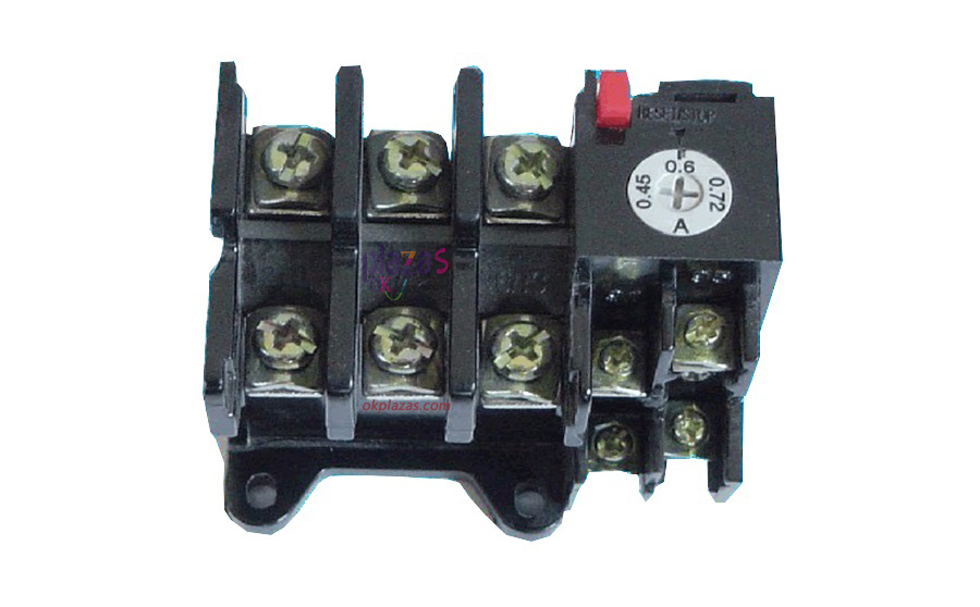
First of all, the main structure of the thermal overload relay is composed of two parts, including the thermal element and the output auxiliary contact. According to the wiring diagram below, we can clearly see that the terminal on the left is the terminal for the relay in the main circuit, which is divided into 3 channels and a total of 6 points, and the terminal on the right is the output auxiliary contact terminal. The thermal components of thermal overload relays are generally made of metal materials with different expansion coefficients, so they will bend when they are heated.
When working, the thermal element and the main circuit in the circuit are connected in series (just like the motor power supply circuit in the motor starter). The specific wiring method of the thermal overload relay is as shown in the figure below, up and down on the left There are 3 contacts in each of the two rows, and each thermal element is connected between the upper and lower terminals. A total of 3 thermal elements are connected in series to the 3 power input wires of the motor. Auxiliary contacts are usually one normally open (NO) and one normally closed (NC), which are suitable for the control loop of the motor starter.
When the motor is overloaded, the current input to the motor will exceed the rated current of the motor, so the thermal element in the thermal overload relay will generate heat and bend according to the excessive current flowing. The internal mechanical structure drives the output contacts to perform switching actions, so as to achieve the purpose of outputting an "overload" signal. The NC contact group of the auxiliary contact of the relay can be connected in series to the power supply circuit of the control circuit (at the same time in series with the stop button). Once the motor is overloaded, the NC contact of the auxiliary contact can immediately cut off the power of the control circuit to realize the motor stop Operation plays a protective role. At the same time, the auxiliary contact NO contact group can be connected to alarm accessories (such as indicator lights), and when the motor stops running due to overload, it can give the reason of the motor stop "overload" prompt.
Thermal overload relay and contactor wiring diagram
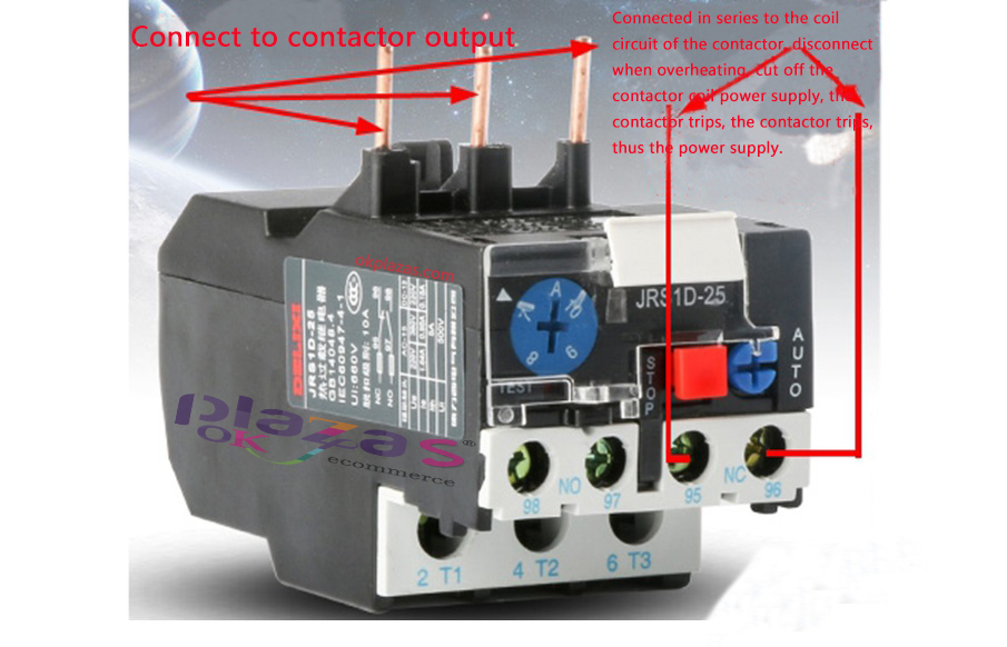
In general, it is 95 in and 96 out.
Wiring method of thermal overload relay with air switch and AC contactor
If you want to connect, we must first understand the function of the device. I believe everyone is very clear about the air switch. The common electrical appliances in life can be seen by opening the household distribution box. If these three equipment are configured according to If the wiring is arranged from top to bottom, it is air switch, contactor, and thermal overload relay.
First of all, the contactor has three pairs of main contacts and a coil (because the voltage specifications of the coil are relatively large, so you must see clearly when connecting, usually AC380V, 220V or DC24) I believe this is not necessary here More details. The contactor also has a pair of normally open contacts and a pair of normally closed contacts according to different models, but there are also designs that are designed to have both normally open and normally closed.
Generally, the normally open contact of the contactor is mainly used for self-locking. Self-locking is the function of locking the device's own circuit. The self-protection previously mentioned means that it can continue to keep its own control circuit working continuously. The normally closed contact of the contactor is generally used in the interlocking mode, and the interlocking means to prevent the contactors from operating at the same time. When there is a forward rotation in the forward and reverse circuit, the reverse rotation is not possible, which requires The normally closed point is used for interlocking. If the forward and reverse rotations operate at the same time, it will cause a short circuit fault.
Secondly, let's talk about thermal overload relays, which usually have a pair of normally open and a pair of normally closed points. From its function, it can mainly protect the circuit from heat. The normally closed point of the thermal overload relay is usually connected to the circuit in series. Once the normally closed point is overloaded, it can be disconnected and the circuit will be cut off. It should be noted here that it is best to adjust the operating current of the thermal overload relay according to the size of the load. If the adjustment is too large, it will not provide protection. On the contrary, if the adjustment is small, it will not work normally. This needs to be controlled. .
Finally, we talk about the specific wiring method of thermal overload relay and air switch according to the specifications of 380V contactor. The three live wires of the air switch are connected to the three pairs of main contacts of the contactor, and then the lower end of the contactor is connected to the thermal relay. At the same time, connect the three terminals at the lower end of the thermal relay to the 380V contactor. Connect a wire from the main contact of the AC contactor to the normally closed contact of the thermal relay, and then connect the other end of the normally closed contact to A1 of the contactor. Then connect a wire power supply from the main contact of the AC contactor to the coil A2 of the contactor. The wiring work is basically completed here, but remember that the main power supply from the contactor must not be the same wire. Below is attached a physical wiring diagram of the thermal overload relay in three-phase power.

Thermal overload relay reset adjustment instructions
Generally, the red button on the front of the device is the stop button, and the blue button is the reset button. There is also a knob for adjusting the current. The reset adjustment method of thermal overload relay can be divided into two kinds, including manual reset and automatic reset.
Relay manual reset adjustment: After the device performs the overload protection action, you must press the reset button with your hand to restore its normally closed contact to the closed state, and you should wait 2 to 3 minutes when you take manual reset It can be done later.
Relay automatic reset adjustment: After the device performs overload protection, the normally closed contact can automatically restore to the closed state, and the automatic reset time will not exceed 5 minutes.
The reset method of the thermal overload relay can be selected by resetting the adjustment screw. Use a flat-blade screwdriver to extend into the adjustment hole on the lower side of the device, and then tighten the reset adjustment screw in a clockwise direction (adjust to the bottom), which is Automatic reset adjustment operation. To return to manual operation, just loosen the adjustment screw counterclockwise to a certain distance.
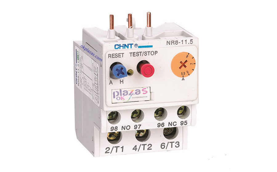
Nowadays, many thermal overload relays are equipped with adjusting knobs on the upper cover, as shown in the figure above. When the adjustment knob is aligned to the H position, it means manual reset, and when it is aligned to the A position, it means automatic reset.
The method for adjusting the current size of the thermal overload relay is to adjust the current size adjustment knob on the front of the device housing according to the actual rated current of the motor, because there are basically clear current scales above.
The above is the thermal overload relay wiring diagram and reset adjustment instructions, I hope to help you.okplazas.com is a professional sales agent for relays and other products. Welcome to email: [email protected] for consultation, and you can also contact WeChat customer service +86-13689242098 online for product consultation!
-
The principle and application field of Autonics panel products (handling)
 June 12, 2021
 -
New product launch SRH1 series single-phase SSR with integrated heat sink
 June 12, 2021
 -
New product launch SRH1 series single-phase SSR with integrated heat sink
 June 12, 2021
 -
Otto protection grade IP69K new product launched Ø18mm cylindrical (SUS316L housing) photoelectric sensor BRQT series
 June 12, 2021
 -
Autonics adds shading motion mode sensor
 June 12, 2021