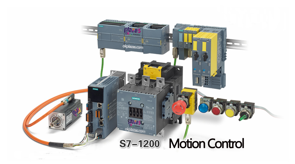
What are the motion control methods of SIMATIC S7-1200
The so-called "motion control (MotionControl)" refers to the process of using the servo system to control the position and speed of the mechanical transmission. For example, control the conveyor belt and cutters of the machine tool to complete accurate workpiece cutting. The motion control system mainly includes: motion controller, servo drive, servo motor and encoder and other components. The motion controller is a PLC CPU with motion control function or a special motion control module; the servo driver is used to receive the command of the motion controller and complete the motion control of the servo motor; the servo motor is the actuator to drive the process axis Carry out movement; the servo motor has a built-in encoder, which can feedback the position of the motor to the servo drive or motion controller to form a closed loop control.
Siemens SIMATIC S7-1200 series PLC integrates motion control functions, which can control the servo drive in a variety of ways. In today's article, let's talk about the motion control modes of S7-1200.
For S7-1200 CPUs with firmware version greater than or equal to V4.1, there are three types of control servo drives
Methods:
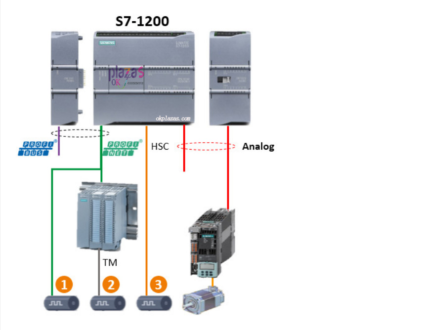
(1)PROFIdrive: PROFIdrive is a drive technology standard based on PROFIBUS or PROFINET bus, which is included in the international standard IEC61800-7. PROFIdrive defines a motion control model, which contains a variety of devices. The devices exchange data through preset interfaces and messages. These messages are called PROFIdrive message frames. Each message frame has a standard structure, and different message frames can be selected according to specific applications. Through the PROFIdrive message frame, the control word, status word, set value and actual value can be transmitted. The schematic diagram of S7-1200 motion control based on PROFIdrive is as follows:
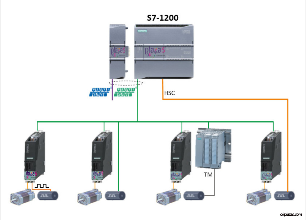
In the above figure, the signal of the built-in encoder of the servo motor can have four feedback methods:
Feedback to the servo drive;
Direct feedback to the CPU via the bus;
Connected to the distributed technology module, the CPU reads data through the bus;
High-speed counter channel directly connected to the CPU;
No matter which method is used, PROFIdrive can form a closed loop control;
(2) PTO method: The full name of PTO is "Pulse Train Output", that is, "Pulse Train Output". The motion controller controls the speed of the servo motor by sending a pulse train with a duty cycle of 50% to the servo drive. Take CPU1215C as an example, it supports a total of four pulse train outputs (Pulse1~Pulse4), and each pulse signal supports four PTO modes, respectively
Yes:
PTO (Pulse A and direction B, pulse A and direction B);
PTO (Count up A and countdown B, count up A and count down B);
PTO (A/B phase-shifted, A/B phase-shift);
PTO (A/B phase-shiftedfourfold, A/B phase-shifted fourfold);
As shown below:
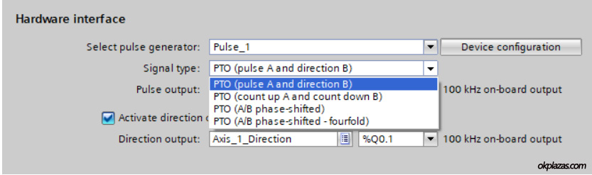
Among them, PTO (Pulse A and direction B) is a more commonly used method. This PTO method uses two outputs of the CPU: one (A) generates high-speed pulse trains, and the other (B) controls the direction of movement of the servo motor. By controlling the frequency generated by the pulse train, the speed of the motor can be controlled.
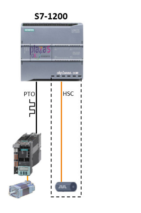
The PTO method can be open-loop control, or the encoder of the motor can be connected to the high-speed counter of the CPU for position counting, thereby forming a closed-loop system. The schematic diagram of S7-1200 PTO-based motion control is as follows:
(3) Analog mode: This mode uses analog signal as the given signal of the servo drive, and controls the speed of the servo motor through the change of the analog signal. Take SINAMICS V90 as an example, it can accept a speed reference signal of ±10V. We can use the signal board "AQ1x12 BIT" of the S7-1200 to output a voltage signal of ±10V. By connecting the signal board output to the V90 signal setting phase, the motion control can be performed in an analog manner.
The analog motion control method must also form a closed-loop system, and the encoder signal can be fed back to the CPU by using a high-speed counter or a bus. The schematic diagram of S7-1200 motion control based on analog is as follows:
Well, the way of motion control of S7-1200 is introduced here first. In future articles, we will introduce the specific content of each control method in depth.
-
The principle and application field of Autonics panel products (handling)
 June 12, 2021
 -
New product launch SRH1 series single-phase SSR with integrated heat sink
 June 12, 2021
 -
New product launch SRH1 series single-phase SSR with integrated heat sink
 June 12, 2021
 -
Otto protection grade IP69K new product launched Ø18mm cylindrical (SUS316L housing) photoelectric sensor BRQT series
 June 12, 2021
 -
Autonics adds shading motion mode sensor
 June 12, 2021