What are the working methods and applications of incremental encoders and absolute encoders
What are the working methods and applications of incremental encoders and absolute encoders
What are the working methods and applications of incremental encoders and absolute encoders
What are the working methods and applications of incremental encoders and absolute encoders?
Incremental encoders output pulses when rotating, and calculate their position through counting devices. When the encoder is not moving or power is off, it relies on the internal memory of the counting device to remember the position. In this way, when the power is off, the encoder cannot move. When the power is applied, the encoder cannot lose the pulse due to interference during the pulse output. Otherwise, the zero point calculated and memorized by the counting device will shift, and this The amount of this offset is impossible to know, only after the wrong production results appear.
The solution is to increase the reference point. Every time the encoder passes the reference point, the reference position is corrected into the memory position of the counting device. Before the reference point, the accuracy of the position cannot be guaranteed. For this reason, in industrial control, there are methods such as first finding the reference point for each operation, turning on the machine, and so on. This method is more troublesome for some industrial control projects, and it is not even allowed to switch on the machine (you must know the exact position after turning on the machine), so the absolute encoder appears.
There are many optical channel engraved lines on the optical code disc of absolute encoder, and each engraved line is in order of 2, 4, 8 and 16 lines. . . . . . Arrangement, in this way, at each position of the encoder, by reading the open and dark of each engraved line, a set of unique binary codes from the zero power of 2 to the n-1 power of 2 (Gray Code), which is called an n-bit absolute encoder. Such an encoder is determined by the mechanical position of the photoelectric code disc, and it is not affected by power failure or interference. Each position determined by the mechanical position of the absolute encoder is unique. It does not need to be memorized, does not need to find a reference point, and does not need to be counted all the time. When it needs to know the position, when to read its position. In this way, the anti-interference characteristics of the encoder and the reliability of the data are greatly improved.
Rotate a single-turn absolute encoder to measure each engraved line of the photoelectric code disk during rotation to obtain a unique code. When the rotation exceeds 360 degrees, the code returns to the original point, which does not comply with the absolute code unique principle. The encoding can only be used for measurement within 360 degrees of rotation, which is called a single-turn absolute encoder. If you want to measure rotation beyond 360 degrees, you must use a multi-turn absolute encoder.
The encoder manufacturer uses the principle of clock gear mechanism. When the center code wheel rotates, another set of code discs (or multiple sets of gears, multiple sets of code discs) are driven by gears, and the number of turns is added to the single-turn encoding. Encoding, in order to expand the measuring range of the encoder, such an absolute encoder is called a multi-turn absolute encoder, it is also determined by the mechanical position code, each position code is unique and does not repeat, without the need to remember. Another advantage of the multi-turn encoder is that due to the large measuring range, the actual use tends to be richer. In this way, it is unnecessary to find the change point during installation. It is enough to use an intermediate position as the starting point, which greatly simplifies the difficulty of installation and debugging.
What are the working methods and applications of incremental encoders and absolute encoders?
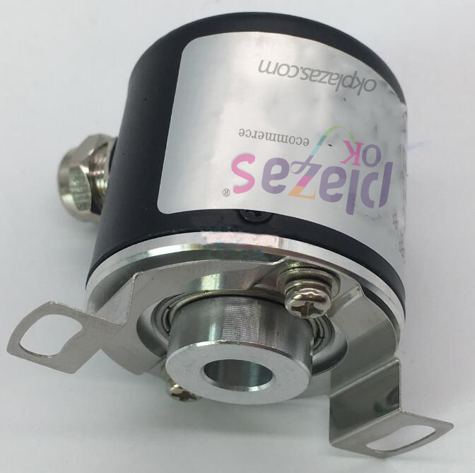
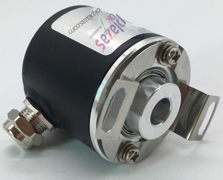
First, the mechanical installation of the absolute value rotary encoder:
The mechanical installation of the absolute rotary encoder has various forms such as high-speed end installation, low-speed end installation, and auxiliary mechanical device installation.
Incremental encoder and absolute encoder, do you know the difference between them and how to use them?
1. High-speed end installation: Installed on the shaft end of the power motor (or gear connection). The advantage of this method is high resolution. Since the multi-turn encoder has 4096 turns, the number of motor turns is within this range, which can be increased by fully using the full range Resolution, the disadvantage is that after the moving object passes through the reduction gear, there is a gear gap error in the back and forth stroke, which is generally used for unidirectional control positioning. In addition, the encoder is directly installed on the high-speed end, and the motor jitter must be small, otherwise the encoder is easily damaged.
2. Low-speed end installation:
Incremental encoder and absolute encoder, do you know the difference between them and how to use them?
It is installed after the reduction gear, such as the shaft end of the hoisting wire rope drum or the shaft end of the last reduction gear. This method has no gear back and forth clearance, the measurement is more direct and the accuracy is higher.
In addition, the mechanical revolution of GPMV0814 is 90 revolutions. This method is more reasonable. If the revolution of the reel exceeds 90 revolutions, you can use 1:3 or 1:4 gear set to adjust to the measurement range of revolutions.
3 Auxiliary mechanical installation, rope-retracting mechanical installation:
What are the working methods and applications of incremental encoders and absolute encoders?
Second, the signal output of the absolute encoder
Absolute encoder signal output has parallel output, serial output, bus type output, and transmission integrated output
1. Encoder parallel output:
The output of the absolute encoder is a multi-digit number (Gray code or pure binary code), and the parallel output means that there are multiple high and low level outputs on the interface to represent the digital 1 or 0. For absolute encoders with low digits , Generally, the digital output is directly in this form, which can directly enter the I/O interface of the PLC or upper computer, the output is instant, and the connection is simple. But parallel output has the following problems:
1. It must be a Gray code, because if it is a pure binary code, there may be multiple bit changes when the data is refreshed, and the reading will cause code errors in a short time.
2. All interfaces must be connected well, because if there is a bad connection point, the potential of that point is always 0, which causes an error code and cannot be judged.
3. The transmission distance cannot be far, generally one or two meters. For complex environments, isolation is best.
4. For a large number of digits, many core cables are required, and good connections must be ensured, which brings engineering difficulties. Similarly, for encoders, there must be many node outputs at the same time, which increases the failure rate of the encoder.
2. Encoder serial SSI output:
Serial output is through an agreement, there is a sequential data output in time, this agreement is called a communication protocol, the physical form of its connection is RS232, RS422 (TTL), RS485, etc. Since the good manufacturers of absolute encoders are all in Germany, most of the serial output is matched with Siemens in Germany, such as SSI synchronous serial output.
3. Encoder fieldbus type output
Fieldbus type encoders are multiple encoders connected together by a pair of signal wires. By setting the address, the signal is transmitted by communication. The signal receiving device only needs one interface to read multiple encoder signals. The signal of the bus-type encoder follows the physical format of RS485, and the arrangement of the signal is called the communication protocol. At present, there are multiple communication protocols in the world, each with its advantages, but not yet unified. There are several commonly used communication protocols for encoders: PROFIBUS- DP; PROFINET; CAN; DeviceNet; Interbus and other bus-type encoders can save connection cables, receiving device interfaces, and have a long transmission distance. In the case of centralized control of multiple encoders, it can also greatly save costs.
4. Encoder transmission integrated output
Some encoders have specific output methods, including analog 4-20mA output, RS485 digital output, and 14-bit parallel output.
The above is about: What are the relevant introductions about the working methods and applications of incremental encoders and absolute encoders! okplazas.com is a high-tech enterprise integrating R&D, production and sales of industrial encoders and high-precision couplings. The company's products have passed CE certification and ROHS certification. Strength casts brand, professional achievement quality.
-
The principle and application field of Autonics panel products (handling)
 June 12, 2021
 -
New product launch SRH1 series single-phase SSR with integrated heat sink
 June 12, 2021
 -
New product launch SRH1 series single-phase SSR with integrated heat sink
 June 12, 2021
 -
Otto protection grade IP69K new product launched Ø18mm cylindrical (SUS316L housing) photoelectric sensor BRQT series
 June 12, 2021
 -
Autonics adds shading motion mode sensor
 June 12, 2021