What is an encoder Introduction to the working principle of the encoder
What is an encoder Introduction to the working principle of the encoder
What is an encoder Introduction to the working principle of the encoder
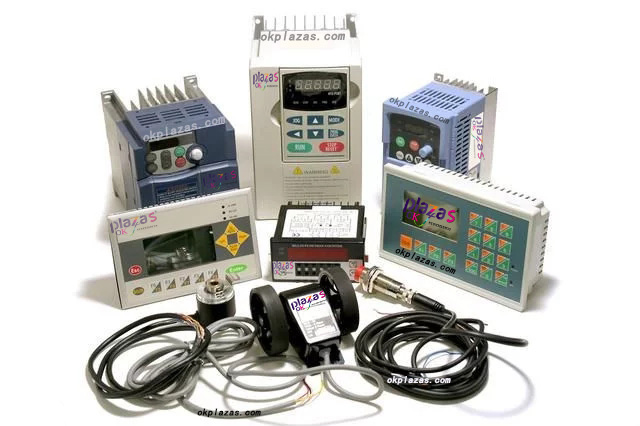
An encoder is a device that compiles and converts a signal (such as a bit stream) or data into a signal form that can be used for communication, transmission and storage. The encoder converts angular displacement or linear displacement into electrical signals. The former is called a code wheel and the latter is called a code ruler.
Encoders can be divided into contact type and non-contact type according to the reading mode; encoders can be divided into two types: incremental and absolute according to the working principle. The incremental encoder converts the displacement into a periodic electric signal, and then converts this electric signal into a counting pulse, and the number of pulses is used to indicate the magnitude of the displacement. Each position of the absolute encoder corresponds to a certain digital code, so its indication is only related to the start and end positions of the measurement, and has nothing to do with the middle process of the measurement.
How the encoder works
The encoder is a rotary sensor that converts the rotation displacement into a series of digital pulse signals. These pulses can be used to control the angular displacement. If the encoder is combined with a gear pin or screw screw, it can also be used to measure linear displacement.
After the encoder generates the electrical signal, it is processed by the digital control CNC, programmable logic controller PLC, control system, etc. These sensors are mainly used in the following areas: machine tools, material processing, motor feedback systems, and measurement and control equipment. The conversion of angular displacement in the ELTRA encoder uses the photoelectric scanning principle. The reading system is based on the rotation of a radial index plate, which is composed of alternating light-transmitting windows and opaque windows. This system all uses an infrared light source to illuminate vertically so that the light projects the image on the plate onto the surface of the receiver, which is covered with a layer of grating, called a collimator, which has the same window as the optical disc. The job of the receiver is to feel the light change produced by the rotation of the disc, and then convert the light change into a corresponding electrical change. Generally, a rotary encoder can also get a speed signal, which has to be fed back to the inverter to adjust the output data of the inverter.
Trouble phenomenon: 1. When the rotary encoder is broken (no output), the inverter cannot work normally and becomes very slow, and after a while the inverter protects and displays "PG disconnection"...the combined action can only take effect. To make the electrical signal rise to a higher level and produce a square wave pulse without any interference, this must be processed by an electronic circuit. The connection between the encoder pg wiring and the parameter vector inverter and the encoder pg must correspond to the encoder pg model.
Generally speaking, the encoder pg model is divided into three types: differential output, open collector output and push-pull output. The signal transmission method must take into account the interface of the inverter pg card, so choose the appropriate pg card model or set it reasonably.

Encoders are generally divided into incremental and absolute types, and there are big differences between them:
In the case of an incremental encoder, the position is determined by the number of pulses counted from the zero mark, while the position of an absolute encoder is determined by the reading of the output code. In a circle, the reading of the output code of each position is unique;
Therefore, when the power is disconnected, the absolute encoder is not separated from the actual position. If the power is turned on again, the position reading is still current and valid; unlike the incremental encoder, the zero mark must be searched.
Encoder manufacturers produce a complete series, which are generally dedicated, such as elevator dedicated encoders, machine tool dedicated encoders, servo motor dedicated encoders, etc., and the encoders are all intelligent, with various parallel The interface can communicate with other devices.
Encoder is a device that converts angular displacement or linear displacement into electrical signals. The former becomes a code wheel and the latter is called a yardstick. Encoders can be divided into contact type and non-contact type according to the read mode. The contact type uses an electric brush to output. A brush touches the conductive area or the insulating area to indicate whether the status of the code is "1" or "0"; the non-contact type receiving sensitive element is a photosensitive element or a magnetic sensitive element. The light-transmitting area and the opaque area indicate whether the code status is "1" or "0".
According to the working principle, encoders can be divided into two types: incremental and absolute.
The incremental encoder converts the displacement into a periodic electric signal, and then converts this electric signal into a counting pulse, and the number of pulses is used to indicate the magnitude of the displacement. Each position of the absolute encoder corresponds to a certain digital code, so its indication is only related to the start and end positions of the measurement, and has nothing to do with the middle process of the measurement.
Rotary incremental encoder outputs pulses while rotating, and knows its position through counting equipment. When the encoder is not moving or the power is cut off, it relies on the internal memory of the counting equipment to remember the position. In this way, when the power is off, the encoder cannot move. When the power is on, the encoder cannot lose the pulse due to interference during the pulse output. Otherwise, the zero point of the counting device will shift, and this deviation There is no way to know the amount of shift, only after the wrong production results appear. The solution is to increase the reference point. Every time the encoder passes the reference point, the reference position is corrected into the memory position of the counting device. Before the reference point, the accuracy of the position cannot be guaranteed. For this reason, in industrial control, there are methods such as first finding the reference point for each operation, turning on the machine, and so on. Such an encoder is determined by the mechanical position of the encoder, and it is not affected by power failure or interference.
The absolute encoder is determined by the uniqueness of each position by the mechanical position. It does not need to be memorized, does not need to find a reference point, and does not need to be counted all the time. When it needs to know the position, when to read its position. In this way, the anti-interference characteristics of the encoder and the reliability of the data are greatly improved.
Since absolute encoders are significantly better than incremental encoders in positioning, they have been increasingly used in industrial control positioning.
Absolute encoders have a large number of output digits due to their high precision. If parallel output is still used, each output signal must be well connected. For more complex working conditions, it must be isolated and the number of connecting cables is large. Bringing a lot of inconvenience and reducing reliability. Therefore, the absolute encoder in the multi-digit output type generally uses serial output or bus type output. The most commonly used serial output of the absolute encoder produced in Germany is SSI (synchronous serial Line output).
Multi-turn absolute encoder. The encoder manufacturer uses the principle of clock gear mechanism. When the center code wheel rotates, another set of code discs (or multiple sets of gears, multiple sets of code discs) are driven by gears, and the number of turns is added to the single-turn encoding. Encoding, in order to expand the measuring range of the encoder, such an absolute encoder is called a multi-turn absolute encoder, it is also determined by the mechanical position code, each position code is unique and does not repeat, without the need to remember.
Another advantage of the multi-turn encoder is that due to the large measurement range, the actual use is often richer, so it is not necessary to find a change point during installation, and a certain intermediate position is used as the starting point, which greatly simplifies the difficulty of installation and debugging. Multi-turn absolute encoders have obvious advantages in length positioning and have been increasingly used in industrial control positioning.
-
The principle and application field of Autonics panel products (handling)
 June 12, 2021
 -
New product launch SRH1 series single-phase SSR with integrated heat sink
 June 12, 2021
 -
New product launch SRH1 series single-phase SSR with integrated heat sink
 June 12, 2021
 -
Otto protection grade IP69K new product launched Ø18mm cylindrical (SUS316L housing) photoelectric sensor BRQT series
 June 12, 2021
 -
Autonics adds shading motion mode sensor
 June 12, 2021