What is the 6-step analysis of the working characteristics and selection of incremental encoders
What is the 6-step analysis of the working characteristics and selection of incremental encoders
What is the 6-step analysis of the working characteristics and selection of incremental encoders
What is the 6-step analysis of the working characteristics and selection of incremental encoders?
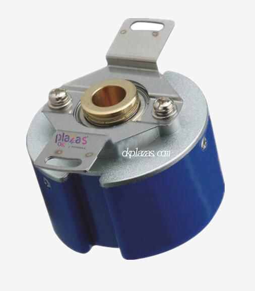
When the incremental encoder shaft rotates, there is a corresponding pulse output. The identification of the direction of rotation and the increase or decrease of the number of pulses need to be realized with the help of the direction circuit and counter at the rear. The counting starting point can be set arbitrarily, and unlimited accumulation and measurement of multiple turns can be realized. When the number of pulses is fixed and the resolution needs to be improved, two signals of 90° phase difference A and B can be used to multiply the original pulse number. We know that the stepper motor itself has no feedback device. In some occasions that require precise control, it needs to be used with feedback devices such as encoders. In order to be close to actual engineering applications, we installed an incremental encoder. In this article, what is our 6-step analysis of the working characteristics and selection of incremental encoders? Let's learn more about the incremental encoder
The material of the incremental encoder code disc varies according to the matching sensitive components. The inner hole of the code wheel is determined by the shaft diameter installed on the measured shaft, the outer diameter of the code wheel is determined by the number of code channels on the code wheel, and the number of code channels is determined by the resolution. If the number of code channels is n, the resolution is 1/2n. The width of the code track is determined by the geometric parameters and physical characteristics of the sensitive element.
What is the 6-step analysis of the working characteristics and selection of incremental encoders?
There are two basic types of angle incremental encoders: absolute encoders and incremental encoders. Corresponding to an absolute encoder is an incremental encoder. Incremental encoders can determine the instantaneous angular position of a shaft relative to a reference point in digital form, and can also be used to measure angular velocity.
What is the 6-step analysis of the working characteristics and selection of incremental encoders? Incremental encoder composition
First; the composition of incremental encoder
Most of the technologies studied for absolute encoder systems are also applicable to incremental encoders, but the composition of the code disc is different. The incremental encoder sets up an inner track and an outer track to the code disc. The outer track has two tracks: the first outer track is an incremental counting track, which sets a sector according to the resolution, that is, there is only one track; The second outer track is the directional track, which has the same number of sectors as the counting track, but has moved half a sector. If a cycle is two sectors (conducting-non-conducting), then the output of the two tracks differs by 90° (electrical angle), or leading, or lagging, used to identify whether it is rotating clockwise or counterclockwise, thus Decide whether the counter counts down or counts up. The inner track is called the reference track. It has only a single marked sector area to provide a reference point. Its output pulse will be used to make the counter return to the encoder's binary code or cyclic code that can indicate the absolute position. "1" output is only the increment of angular displacement. The following figure shows the relationship between the track and output of an incremental encoder.
Second; what is the 6-step analysis of the working characteristics and selection of incremental encoders? Sensitive element of incremental encoder
The sensitive element of the incremental encoder can adopt any of the absolute encoders. It can be contact type (brush) or non-contact type (photoelectric system or magnetoelectric system). Therefore, they must be compatible with the code disc.
Third: Incremental encoder counter Since the incremental encoder calculates the increment of angular displacement, in order to calculate the actual size and direction of the angular displacement relative to a certain reference position, a counter must be set. The counting pulse sent to the counter is output by the Schmitt trigger circuit.
The working principle of incremental encoder
The schematic diagram of the incremental encoder and the truth table of the Schmitt trigger. When considering the addition count, the movement direction of its sensitive element is from left to right. The transition of the output of the counting track from logic "0" to logic "1" is added to the J input of the flip-flop, and only when the K input of the direction track is logic "0", this jump The change can trigger the output Q of the flip-flop to logic "1". This situation only occurs in the "addition" counting direction. The flip-flop must be reset to zero with the transition of the "direction" output from logic "0" to logic "1". Therefore, only when the "count" and direction pulses are alternately fed back to the trigger, the "addition" count pulse added to the counter is started. This process can be verified by studying the cases where the labels (4 states) in the truth table are 1, 2, 3, and 4. According to the fact that the direction pulse is negative at the moment when the flip-flop changes state, it can be used to send the "adding count" signal (logic "1") to the counter itself through an inverter. In the case of "subtraction counting", the "count" pulse changing from logic "0" to logic "1" also generates a single output pulse, but it only occurs when the direction "pulse" is logic "1". At this moment, the counter receives a "subtraction" instruction. Use the truth table to verify positions A, B, C, and D to verify that this logic is correct. When using an incremental encoder to measure speed, please note that the maximum speed range is limited by the single pulse width generated by the trigger. The pulse width should be less than half of the time occupied by one bit. The typical width of a single pulse is 4~6μs, and its rise time and recovery time are 200ns. For an encoder with 5000 pulses per revolution, the maximum speed is 2000r/min; for an encoder with 1200 pulses per revolution, the maximum speed is about 5000r/min. That is to say, when using a code wheel alone, the speed range and resolution must be considered comprehensively.
Fourth; connection of incremental encoder and PLC
The pulse signal output by the incremental encoder needs to be connected to the high-speed counter of the PLC. Some PLC CPU modules integrate high-speed counters (for example, S7-200 SMART, S7-1200 series), and the output signal of the encoder can be directly connected to the integrated high-speed counting channel of the CPU module; some CPUs do not integrate high-speed counters. Counter (such as S7-300/1500 series). In this case, a special high-speed counting module is required.
Fifth; What is the 6-step analysis of the working characteristics and selection of incremental encoders? How to select the incremental encoder
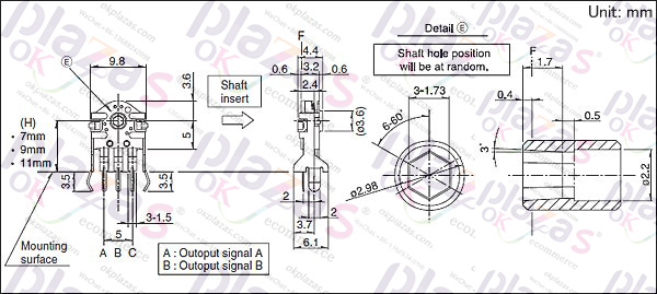
1. Mechanical installation dimensions, including positioning stop, shaft diameter, installation hole position; cable outlet method; installation space volume; whether the working environment protection level meets the requirements.
2. Resolution, that is, the number of pulses output per revolution when the encoder is working, and whether it meets the design and use accuracy requirements.
3. Electrical interface. Common encoder output methods include push-pull output (F type HTL format), voltage output (E), open collector (C, common C is NPN tube output, C2 is PNP tube output), long-line driver Output. Its output mode should match the interface circuit of its control system.
Sixth; What is the 6-step analysis of the working characteristics and selection of incremental encoders? How to choose an incremental encoder?
1. Incremental rotary encoders have different resolutions, which are measured by the number of pulses generated per revolution. The number ranges from 100 to 10000 or higher. The more pulses, the higher the resolution; this is an important basis for selection one.
2. Incremental encoders usually have three signal outputs (there are six signals for differential): A, B and Z, generally using TTL level, A pulse in the front, B pulse in the back, A and B pulses are 90 degrees apart, each The circle sends out a Z pulse, which can be used as a reference mechanical zero position. Generally use A to lead B or B to lead A to determine direction.
-
The principle and application field of Autonics panel products (handling)
 June 12, 2021
 -
New product launch SRH1 series single-phase SSR with integrated heat sink
 June 12, 2021
 -
New product launch SRH1 series single-phase SSR with integrated heat sink
 June 12, 2021
 -
Otto protection grade IP69K new product launched Ø18mm cylindrical (SUS316L housing) photoelectric sensor BRQT series
 June 12, 2021
 -
Autonics adds shading motion mode sensor
 June 12, 2021