What is the encoder interface circuit and working principle
What is the encoder interface circuit and working principle
What is the encoder interface circuit and working principle?
Common output forms of encoders:
First, the type of open collector:
Usually the encoder does not provide R1 resistance, so an internal circuit is needed to achieve the pull-up or pull-down level.
Encoder interface circuit and MM440 connection
Second, the push-pull output type:
When the output signal "1" is turned on, and when the output signal is "0", T2 is turned on. In this circuit, the output current flows in and out of two directions, so when the cable is extended, the waveform distortion is small, and the cable can extend to about 100 meters. The power supply is DC5-30V, the maximum push-pull current is 30mA
Encoder interface circuit and MM440 connection
Third, the line driver output type:
The line drive output is designed according to the RS-422A standard data transmission circuit. The twisted pair can be used for long-distance transmission, up to 1200m.
What is the encoder interface circuit and working principle?
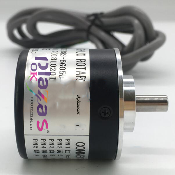
The encoder output signal includes phase a, phase B and phase Z. The direction can be judged by phase a and phase B, and the mechanical origin (reference position) is determined by phase Z.
When the motor rotates, the encoder outputs a-phase, B-phase and Z-phase pulse signals to the driver.
The direction of rotation can be judged by phase A and phase B.
The mechanical origin (reference position) can be determined by the Z phase. The Z phase is 1ppr and is used as an origin sensor.
There are 1, 2, 4 output signal counting methods. The number of pulses per revolution becomes the resolution.
Resolution: pulse rotation. Unit: The higher the resolution of PPR (pulse rotation), the higher the control accuracy.
The smallest control unit of the servo motor is 1 pulse.
-
The principle and application field of Autonics panel products (handling)
 June 12, 2021
 -
New product launch SRH1 series single-phase SSR with integrated heat sink
 June 12, 2021
 -
New product launch SRH1 series single-phase SSR with integrated heat sink
 June 12, 2021
 -
Otto protection grade IP69K new product launched Ø18mm cylindrical (SUS316L housing) photoelectric sensor BRQT series
 June 12, 2021
 -
Autonics adds shading motion mode sensor
 June 12, 2021