What is the principle of vector control and how to use the inverter for closed-loop control
What is the principle of vector control and how to use the inverter for closed-loop control
What is the principle of vector control and how to use the inverter for closed-loop control
The so-called closed-loop control of the frequency converter refers to the output of the frequency converter to the motor and the mechanical equipment driven by the motor. The encoder or pressure and flow sensors are used to feed back the speed, pressure, and flow of the motor to the frequency converter for comparison and calculation of two values. , So that the output of the inverter is infinitely close to the more accurate set value. As long as the inverter's functions are preset and the inverter with closed-loop control function, it can be realized by configuring the corresponding encoder or sensor according to the user manual provided by it.
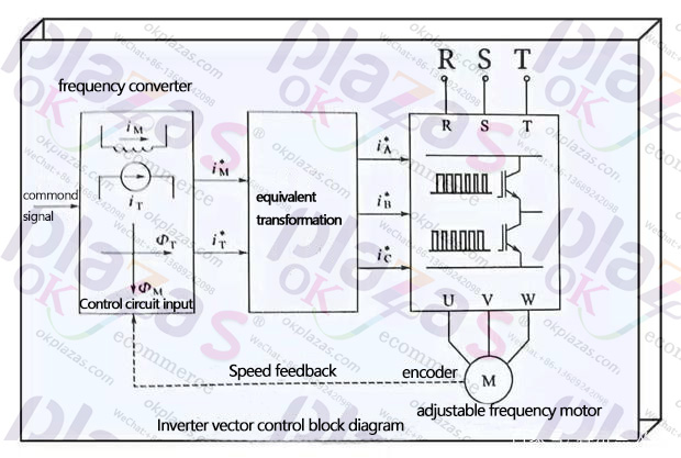
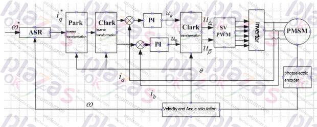
The above is a vector control block diagram of the inverter. According to the above figure, let us briefly talk about what is the vector control mode of the inverter. Simply put, vector control is to imitate the speed regulation characteristics of a DC motor, so that the speed of a three-phase asynchronous AC motor can also be adjusted by controlling two vertical ⊥ DC magnetic fields.
①Processing of a given signal; In the control circuit of the frequency converter, the given signal is analogously decomposed into two rotating vertical DC magnetic field signals, which are called the magnetic field component it and the torque component im to simulate the DC motor Two magnetic fields.
② Carry out equivalent transformation; according to the basic parameters of the motor, carry out a series of equivalent transformations on the mutually perpendicular rotating DC magnetic field signals, and transform them into three-phase inverter bridge control signals iA*, iB* and iC*, as shown above. When the given signal changes, it adjusts the torque component in the DC magnetic field, so as to obtain and simulate the speed regulation characteristics. Among them, the feedback function of the speed is to keep the speed of the motor driven by the inverter strictly in accordance with the set speed value of the inverter. Therefore, the mechanical characteristics of the motor are relatively hard, and it has a high dynamic response capability.
③No speed vector control; Since the core of vector control technology is equivalent conversion, the speed feedback signal is not a necessary condition for equivalent. Therefore, a vector control method without feedback signal appears. The so-called feedbackless vector control, but the user does not need to install encoders or sensors, etc., and does not mean that the inverter is in an open-loop running state.
Different inverters have different function codes. Here, just take a look at the manual of the inverter you use.
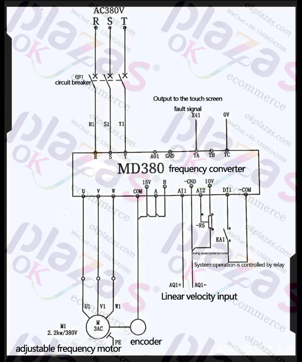
The application circuit diagram of MD380 high-performance vector inverter in the actual circuit above. The motor driven by the frequency converter in the above figure has an encoder attached to the motor shaft to rotate synchronously with the motor. At this time, the encoder can collect its dynamic speed according to the speed of the motor anytime and anywhere, and feedback to the frequency converter in time. PG card.
MD380 inverter supports 4 types of encoders, namely "differential encoder", "UVW encoder", "resolver", "open-loop collector encoder" and "wire-saving encoder". The closed-loop vector control with sensor (F0-0=1) can greatly improve the speed regulation performance of the inverter. It only needs to install an encoder on the shaft of the motor, and the signal collected by the encoder is passed through the PG card (encoding Signal interface card) to feedback to the inverter.
Here to share with you several setting methods of MD380 series inverter; According to the actual type of encoder used, you need to set different encoder-related parameters, taking motor parameter group 1 as an example, the description is as follows;
① When it is a differential encoder, F1-27 sets the number of encoder lines, and F1-28 is set to 0; ABZ incremental encoder.
②For UVW encoder, F1-27 sets the number of encoder lines, F1-28 is set to 1; UVW incremental encoder.
③When it is a resolver, F1-28 is set to 2; resolver.
④ When it is an open collector encoder, F1-27 sets the number of encoder lines, and F1-28 is set to 0; ABZ incremental encoder.
⑤When it is a wire-saving UVW encoder, F1-27 sets the number of encoder lines, and F28 is set to 4; wire-saving UVW encoder.
In addition to setting the above parameters, set this item to the corresponding setting range in F0-01 (first motor control mode) of the function code. There are three settings in this project (0; vector control without speed sensor "SVC", 1; vector control with speed sensor "FVC", 2; V/F control).
In fact, to put it bluntly, playing with inverters is a process where practice makes perfect. There is no big deal as long as you do it with your heart. Because want to be a technical electrician or an ordinary electrician, the money is different.
-
The principle and application field of Autonics panel products (handling)
 June 12, 2021
 -
New product launch SRH1 series single-phase SSR with integrated heat sink
 June 12, 2021
 -
New product launch SRH1 series single-phase SSR with integrated heat sink
 June 12, 2021
 -
Otto protection grade IP69K new product launched Ø18mm cylindrical (SUS316L housing) photoelectric sensor BRQT series
 June 12, 2021
 -
Autonics adds shading motion mode sensor
 June 12, 2021