What is the purpose of coupling alignment What are the methods for coupling alignment
What is the purpose of coupling alignment What are the methods for coupling alignment
What is the purpose of coupling alignment What are the methods for coupling alignment
What is the purpose of coupling alignment? What are the methods for coupling alignment?
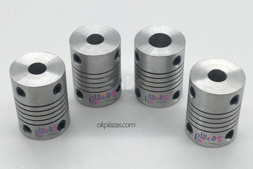
Coupling is an indispensable connecting device between shafts and shafts in operating machinery. The purpose of alignment is to make the center lines of the driving shaft and the driven shaft on the same straight line when the machine is working. The alignment accuracy of the coupling concentricity is related to whether the machine can operate normally, and directly affects the running quality of the equipment, which is especially important for high-speed machines. Therefore, finding the concentricity of the coupling is one of the most important processes in the installation of operating equipment.
First, the purpose of coupling alignment
If the center lines of the two shafts connected by the coupling do not coincide, the equipment will vibrate during operation, leading to increased bearing temperature and wear, and even violent vibration of the entire equipment. Some parts will be damaged instantaneously, causing equipment failure and instability. Therefore, the purpose of coupling alignment mainly includes the following aspects:
1) Try to minimize the vibration and noise caused by the misalignment of the two axes or the relative tilt.
2) Avoid extra radial load between shaft and bearing.
3) Ensure that the axial displacement of each shaft is not hindered by the other side.
Second, the coupling alignment method
The two halves of the coupling are required to be in parallel and concentric accurate positions, and the center lines of the two shafts are on a straight line. It can be adjusted by adding or subtracting shims on the top of the motor and reducer. In the specific adjustment process, the center lines of the two coupling halves cannot be completely on the same axis. Therefore, an error range must be determined when installing and adjusting the coupling. Several common coupling coaxiality and end clearance adjustment standards are now sorted out.
Third, find the right measuring method for the coupling
When the coupling is aligned, it mainly measures radial displacement (or radial clearance) and angular displacement (or axial clearance). Radial displacement is measured with a ruler and feeler gauge, and angular displacement is measured with a plane gauge and a wedge gap gauge. The method is intuitive, but the accuracy is not low. It is usually only used for soft low-speed machines that do not require accurate alignment. Use center card and dial gauge to measure the radial direction of the coupling
Clearance and axial clearance are suitable for precision instruments and high-speed machine tools that require accurate alignment. It is intuitive to operate, low precision, and widely used. Measurement methods include two-meter measurement method, three-meter measurement method (also called two-point measurement method), five-meter measurement method (also called four-point measurement method), and single-meter measurement method. The measurement method of the hot-dip galvanizing production line mainly adopts the double-meter measurement method.

What is the purpose of coupling alignment? What are the methods for coupling alignment?
At present, the coupling is in the cold state and the manual cranking is under no load. Under the operating conditions of mechanical equipment, changes in the shaft center position caused by the load, thermal expansion and oil film support of the sliding bearing must be considered. Therefore, the influence of opening, westward shift and reserved westward shift on alignment adjustment should be considered as much as possible when calculating.
It can meet the technical requirements of the same (concentric and parallel) centerlines of the two shafts under the condition of time-lapse operation with load. When installing large-scale units, some give experience curves of various mechanical equipment under different working conditions, and find out the data values of cold state and no-load detection by looking up tables or calculations.
Experienced installers can also draw some empirical data from practice. In short, for the installer, it is necessary to consider the change of the shaft center position of the bearing position when the mechanical equipment changes from cold to hot, from no load to full load, to ensure that the equipment is continuously running under load in an ideal centering state. The smaller the deviation of the center lines of the two shafts, the more accurate the alignment, the better the operating conditions of the mechanical equipment, and the longer the service life.
-
The principle and application field of Autonics panel products (handling)
 June 12, 2021
 -
New product launch SRH1 series single-phase SSR with integrated heat sink
 June 12, 2021
 -
New product launch SRH1 series single-phase SSR with integrated heat sink
 June 12, 2021
 -
Otto protection grade IP69K new product launched Ø18mm cylindrical (SUS316L housing) photoelectric sensor BRQT series
 June 12, 2021
 -
Autonics adds shading motion mode sensor
 June 12, 2021