What should be paid attention to when installing and debugging the rotary incremental encoder
What should be paid attention to when installing and debugging the rotary incremental encoder
What should be paid attention to when installing and debugging the rotary incremental encoder
What should be paid attention to when installing and debugging the rotary incremental encoder?
Rotary incremental encoders generally have two different output modes: incremental and absolute. Incremental rotary encoders generally pass the output pulse signal to the PLC high-speed counter to count the output pulse signal. okplazas.com encoder introduces you about: What should be paid attention to when installing and debugging the rotary incremental encoder?
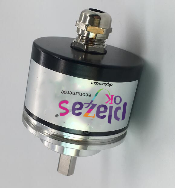
What should be paid attention to during installation and debugging of rotary incremental encoder? Rotary incremental encoder
The connection of rotary incremental encoder generally has five leads, one is com terminal line, the other is power line, and the other three are pulse output lines. First connect the power terminal to the com terminal of the encoder, and then connect the power terminal of the encoder. At this time, the com terminal of the encoder is connected to the PLC input com terminal, and the A, B, and Z two-phase pulse output lines are directly connected to the PLC input terminal, and A and B are pulses with a difference of 90 degrees. Finally, the incremental rotary encoder is also equipped with a shielded wire, and the grounding of the shielded wire can effectively improve the anti-interference ability.
Important: When the working voltage is different from the PLC input voltage, it should be noted that the voltage of the internal power supply must be lower than dc30v. If the working voltage exceeds this working voltage, the encoder may be damaged.
What should be paid attention to when installing and debugging the rotary incremental encoder? Installation steps of rotary incremental encoder. First of all, the encoder coupling should be installed first. At this time, the coupling is fixed with each shaft of the encoder by tightening the screws. However, encoders with springs or mechanical devices can eliminate shock, vibration or deflection of the motor shaft.
Secondly, the next step is to perform wiring operations. Incremental rotary encoders generally have five leads, and each lead has a different function. One is a com port line, the other is a power connection line, also called OC output type, and the other three are pulse output lines. Then the power port has positive and negative sides. However, in the encoder wiring connection, the negative power port is connected to the COM port of the encoder. Secondly, the negative power port and the encoder power port are connected to each other. The remaining three pulse output lines are respectively connected to the output terminals of a, B, C and PLC.
Third, after the encoder wiring is completed, it cannot be used immediately. It is necessary to check whether the encoder installation complies with the standard. If the encoder installation is loose or unstable, check whether the encoder wiring is in contact or connected firmly. Otherwise, these installation details will be ignored, which will cause the encoder to malfunction during use.
When the encoder is installed on site, it is not allowed to install it with high- and dry interference source equipment such as inverters, transformers, solenoid valves, etc., with a distance of 10cm or install metal partitions for isolation. When the module that communicates with the encoder is installed in the electrical cabinet, it cannot be installed with high interference source components such as inverters and contactors or switching components, as these components are often disconnected. Spacing 3cm, or add metal partition to isolate.

What should be paid attention to when installing and debugging the rotary incremental encoder? Rotary incremental encoder installation details
The installation and debugging of the rotary incremental encoder must strengthen the inspection of the connection point of the rotary encoder port, strengthen the problem of firm installation, and prevent the encoder from loosening during use and causing malfunction. When the encoder is fixed by tightening the screws, do not tighten it too tightly, otherwise the encoder cannot be rotated during use. During the wiring process of the encoder installation, attention should be paid to the wiring sequence of the encoder, so as to avoid the overcurrent of the encoder and cause malfunction when the cross connection is reversed.
-
The principle and application field of Autonics panel products (handling)
 June 12, 2021
 -
New product launch SRH1 series single-phase SSR with integrated heat sink
 June 12, 2021
 -
New product launch SRH1 series single-phase SSR with integrated heat sink
 June 12, 2021
 -
Otto protection grade IP69K new product launched Ø18mm cylindrical (SUS316L housing) photoelectric sensor BRQT series
 June 12, 2021
 -
Autonics adds shading motion mode sensor
 June 12, 2021