Working principle of liquid level sensor and wiring diagram
Working principle of liquid level sensor and wiring diagram
The liquid level sensor is also called the liquid level switch, as the name implies, is a switch used to control the liquid level. From the form, it is mainly divided into contact type and non-contact type. Non-contact type such as capacitive liquid level switch, contact type such as: float type liquid level switch, electrode type liquid level switch, electronic liquid level switch, capacitive liquid level switch can also be realized by contact method.
1. The magnetic flap level gauge is also called the magnetic float level gauge and the magnetic flip column level gauge.
Working principle: The connecting device principle is developed based on the buoyancy principle and the magnetic coupling effect. When the liquid level in the measured container rises and falls, the permanent magnet in the float is transferred to the magnetic turning column indicator panel through the magnetic coupling, turning the red and white The column turns over 180°, when the liquid level rises, the turning column turns from white to red, when the liquid level drops, the turning column turns from red to white. The red and white junction on the panel is the actual height of the liquid level in the container, thus achieving the liquid level display.
2. Float level gauge
Working principle: The structure of the float level gauge is mainly designed and produced based on the principles of buoyancy and static magnetic field. The position of the floating ball with magnet (referred to as the floating ball) in the measured medium is affected by buoyancy: the change of liquid level causes the change of the position of the magnetic float. The magnets and sensors (reed switches) in the floating ball change the number of components (such as fixed-value resistors) connected in series to the circuit, which in turn changes the electrical quantity of the meter circuit system. That is, the change in the position of the magnetic float causes a change in the electrical quantity. Reflect the liquid level in the container by detecting the change of electrical quantity.
3. Steel belt level gauge
Working principle: It is designed and manufactured using the principle of mechanical balance. When the liquid level changes, the original mechanical balance will reach a new balance through the movement of the steel belt under the disturbance of the float by the buoyancy force. The liquid level detection device (float) drives the steel belt to move according to the liquid level, and the displacement transmission system drives the transmission pin to rotate through the movement of the steel belt, and then acts on the counter to display the liquid level.
4. Radar level gauge
Working principle: The radar level gauge is a measuring instrument based on the time travel principle. The radar wave runs at the speed of light, and the running time can be converted into a level signal by electronic components. The probe sends out high-frequency pulses and propagates along the cable probe. When the pulses meet the surface of the material, they are reflected back and received by the receiver in the meter, and the distance signal is converted into a level signal.
5. Magnetostrictive level gauge
Working principle: When the sensor of the magnetostrictive level gauge is working, the circuit part of the sensor will excite a pulse current on the waveguide wire, and when the current propagates along the waveguide wire, a pulse current magnetic field will be generated around the waveguide wire. The sensor rod of the magnetostrictive liquid level gauge is equipped with a float, which can move up and down along the rod with the change of liquid level. There is a set of permanent magnetic rings inside the float. When the pulse current magnetic field meets the magnetic ring magnetic field generated by the float, the magnetic field around the float changes so that the waveguide wire made of magnetostrictive material generates a torsional wave pulse at the position of the float. This pulse moves along at a fixed speed. The waveguide wire is passed back and detected by the inspection agency. By measuring the time difference between the pulse current and the torsional wave, the position of the float, that is, the position of the liquid surface, can be accurately determined.
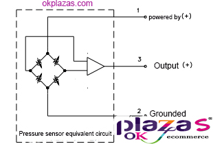
Liquid level sensor, the general output signal is current 4-20MA, 0-20MA, or voltage 0-5V, 1-5V, 0-10V, etc., usually current type is two-wire or four-wire system, voltage three-wire system output. At present, many of them do not have a 24VDC power supply, most of which are 10V. Some transmitters with larger power consumption cannot be driven by a 10VDC power supply, so they can only provide an external power supply of 24VDC. In this way, the liquid level sensor has four terminals: power supply +, power supply -, feedback + and feedback -.
The current type two-wire wiring method of the liquid level sensor wiring: power supply +== power supply+; signal +== feedback+, power supply -== feedback -, if it is not remote transmission, only need to connect 24V voltage +, -, if remote transmission is required Need to form a loop, such as 24V+ connected to pressure gauge+, pressure gauge-connected to 4-20mA+, 4-20mA- connected to 24V-, there may be terminals in the middle, please look at the circuit diagram.
The voltage type three-wire wiring method of the liquid level sensor wiring: power supply +== power supply +; power supply-(signal -) = = power supply -; signal + = = feedback +, power supply-(signal -).
The four-wire wiring method of liquid level sensor wiring: power supply +== power supply+; power supply -== power supply-; signal +== feedback+, signal -==feedback-.
-
The principle and application field of Autonics panel products (handling)
 June 12, 2021
 -
New product launch SRH1 series single-phase SSR with integrated heat sink
 June 12, 2021
 -
New product launch SRH1 series single-phase SSR with integrated heat sink
 June 12, 2021
 -
Otto protection grade IP69K new product launched Ø18mm cylindrical (SUS316L housing) photoelectric sensor BRQT series
 June 12, 2021
 -
Autonics adds shading motion mode sensor
 June 12, 2021