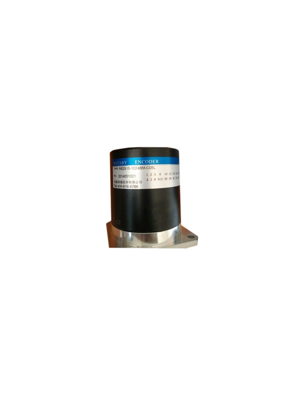


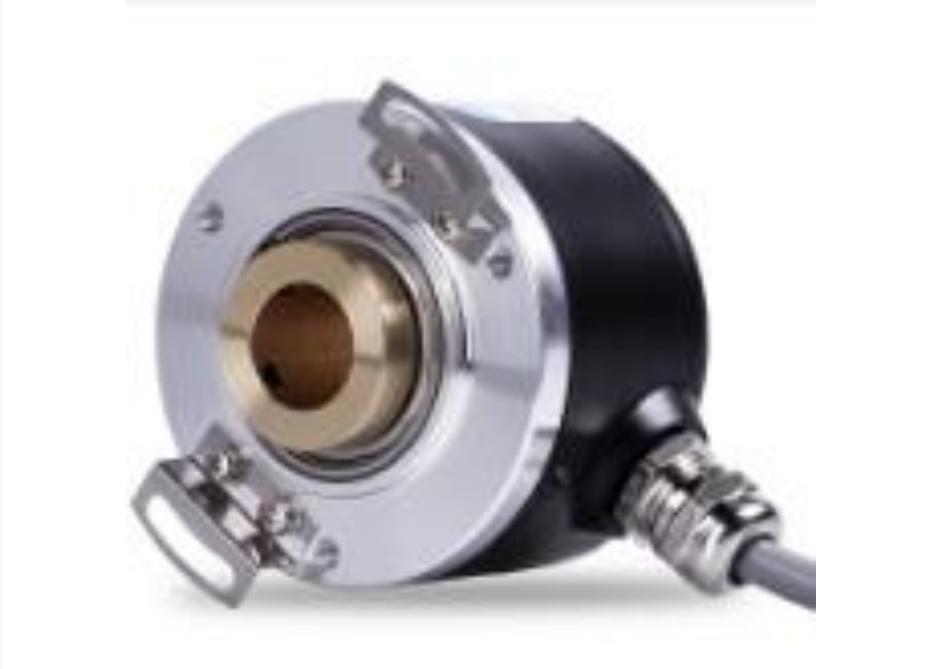
Roundss Encoder R62S15-1024BM-C05L
In addition to the two phases A and B (the phase difference of the signal sequence of the A and B channels is 90 degrees), the general encoder output signal also outputs a zero pulse Z per revolution.
R62S15-1024BM-C05L sensor encoder zi4c
In addition to the two phases A and B (the phase difference of the signal sequence of the A and B channels is 90 degrees), the general encoder output signal also outputs a zero pulse Z per revolution.
When the spindle rotates in a clockwise direction, the A channel signal is before the B channel; when the spindle rotates counterclockwise, the A channel signal is after the B channel. Therefore, it is judged whether the main shaft is rotating forward or backward.
R62S15-1024BM-C05L sensor encoder
There is no need to perform a return to origin at startup. In addition, when the symbol cannot be read due to high-speed rotation, if the rotation speed is reduced, the correct data can be read. In addition, the correct rotation data can be read even when the power is turned off due to a power failure or the like. Rotating the disk with the pattern written, the light passing through the slit can be alternately transmitted and blocked according to the pattern. The transmitted light can be converted into electric current by the light receiving element, and after waveform shaping, it becomes a digital signal. The number of incremental signal pulses or value positions that are output when the axis rotates once. Number of output signals in incremental output phase. Including 1 phase type (A phase), 2 phase type (A phase, B phase), 3 phase (A phase, B phase, Z phase). The Z-phase output is once the signal for the origin is output once. When the output phase difference axis rotates, the ratio of the time offset in the rising or falling of the A-phase and B-phase signals to the signal cycle time, or the electrical angle represents the signal cycle as 360.
Among them, the analog quantity (4~20mA) output is more convenient to use, but the accuracy is sacrificed. Which rotary photoelectric encoder has good price and quality? It is recommended to choose Wenzhou Enguang Electric Co., Ltd., which is an enterprise engaged in the development, production and sales of intelligent instruments. Enguang's products in angular displacement measurement, resolver digital conversion, and weighing force measurement are at the same level in the same industry. In angular displacement measurement: first promote its high reliability, using self-aligning machine and resolver as angular displacement Detecting components, developed and produced a series of angle sensors, resolver-digital converters, angle transmitters, and angle displays to solve the reliability problems of other types of angular displacement measurement. In terms of weighing force measurement: original multiple advanced practical technologies, automatic calibration, non-linear correction technology, convenient for users to use, meet the functional requirements of on-site quick commissioning, and make your weighing system successfully calibrated. An encoder is a sensor used for motion control.
Its design can be widely applied to the requirements of conveying technology, and its application fields include automobile manufacturing, food and beverage, logistics and warehousing, and electrical circuits. The application of the rotary encoder in the circuit is mainly the use of a single-chip microcomputer for pulse recognition of the encoder. Specifically, it is to look at the phase difference between A and B, A is ahead of B or lagging, to determine whether the encoder is forward or reverse, which is called the application of the rotary encoder through the direction recognition circuit. The method of detecting the linear displacement of the rotary encoder is as follows: Use the "flexible coupling" to directly couple the rotary encoder with the main shaft of the power device that drives the linear displacement. Use small gear (straight gear, bevel gear or worm gear) box to couple shaft with power unit. Use gears rotating on a straight rack to transmit linear displacement information. Obtain the linear displacement information on the sprocket of the transmission chain. Obtain linear displacement information on the timing belt of the timing belt wheel. Use a rotary encoder equipped with a magnetic roller to obtain displacement information on a linearly displaced flat steel surface (to avoid slippage.
It has the characteristics of high precision, large range measurement, fast response and digital output; small size, light weight, compact structure, convenient installation, simple maintenance and reliable work. Encoders are classified by measurement function, including angular displacement, linear displacement and speed sensors; by measurement methods, there are linear encoders, angle encoders, and rotary encoders; they are classified by signal principle, and there are incremental encoders. , Type encoder; divided by the type of shaft, there are shaft type and sleeve type (the shaft sleeve type has half hollow type, full hollow type, large shaft diameter type); divided by shape characteristics and mounting flange, there is a synchronization method Lan, clamping flange, compact. Incremental Rotary Encoder The core component of the incremental encoder is a photoelectric code disc with a shaft in the center, on which there are ring-shaped, dark engraved lines. Incremental encoders directly use the principle of photoelectric conversion to output three sets of square wave pulses A, B, and Z phases; A and B pulses have a phase difference of 90º, so that the direction of rotation can be easily judged, and the Z phase is one per revolution. pulse.
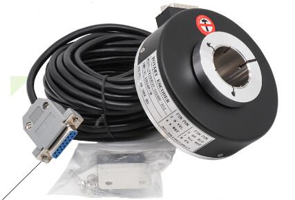
The signal receiving device interface of the encoder should correspond to the encoder. Signal connection—The pulse signal of the encoder is generally connected to the counter, PLC, and computer. The modules connected to the PLC and the computer are divided into low-speed modules and high-speed modules, and the switching frequency is low or high. Such as single-phase connection, used for single direction counting and single direction speed measurement. A.B two-phase connection, used for forward and reverse counting, judgment of forward and reverse and speed measurement. A, B, Z three-phase connection, used for position measurement with reference position correction. A, A-, B, B-, Z, Z- connection, because of the connection with symmetrical negative signal, in the subsequent differential input circuit, the common mode noise is taken only the useful differential mode signal, so it is anti-interference Strong ability and can transmit over long distances. For TTL encoders with symmetrical negative signal output, the signal transmission distance can reach 150 meters. The rotary encoder is composed of precision components, so when it is subjected to a large impact, the internal function may be damaged, so full attention should be paid to it in use.
The role played in our lives. It uses photoelectric, electromagnetic, capacitive or inductive sensing principles to detect the mechanical position and changes of objects, and convert this information into electrical signals and output them as feedback for motion control, which is transmitted to various motion control devices. With the continuous development of industrial control, the demand for selecting encoders is getting higher and higher. In industrial control, rotary encoders are generally mainly used for proximity switches, photoelectric switches and other devices. Rotary encoder has the characteristics of high reliability, high environmental adaptability, and high control performance. Rotary encoder makes the system control running at low speed, in fact, it can better improve work efficiency and become the majority of customers. It can be widely used in various small machinery and equipment supporting industries such as food packaging and textiles. Informationization, in addition to positioning, the control room can also know its specific location; flexibility, positioning can be flexibly adjusted in the control room. Convenience, safety and longevity of on-site installations: a rotary code for the size of the fist.
The number of pulses output by the rotary encoder for one revolution is usually the same as the number of slots in the grating inside the rotary encoder for optical rotary encoders (the number of output pulses can also be increased to twice the number of slots on the circuit. 4 Times).
The resolution means that the main shaft of the rotary encoder rotates once, and the equal fraction of the position data is read out. Value type is not output in pulse form, but in code form to express the current spindle position (angle). Different from the incremental type, it is equivalent to the "output pulse/revolution" of the incremental type.
This method is troublesome for some industrial control projects, and it is not even allowed to switch on the machine (you must know the exact position after turning on the machine), so the encoder appears.
Type rotary photoelectric encoder, because of its every position, anti-interference, no power-down memory, has been more and more widely used in angle, length measurement and positioning control in various industrial systems.
Use a "retractable steel wire assembly" similar to a "steel tape" to connect to a rotary encoder to detect linear displacement information (the error of laminated winding must be overcome in data processing). Similar to 7, use a "retractable steel wire assembly" with a small torque motor to connect to a rotary encoder to detect linear displacement information (currently similar products in Germany have complex structures and almost no stack winding errors). Rotary encoder installation steps: thread the coupler onto the shaft. Do not use screws to fix the coupler and shaft. Step 2: Fix the rotary encoder. When the shaft of the encoder is connected with the coupler, the insertion amount cannot exceed the following values. E69-C04B type coupler, insertion amount 5.2mm; E69-C06B type coupler, insertion amount 5.5mm; E69-Cl0B type coupler, insertion amount 7.lmm. Step 3: Fix the coupler. The tightening torque cannot exceed the following values. E69-C04B type coupler, tightening torque 2.0kfg·c.
And has the ability to simulate a large number of pulses of the encoder. This is thanks to the interpolation of sine and cosine signals, which provides a calculation method for the rotation angle. This method can obtain a high multiplier of the basic sine, for example, from 1024 sine wave encoders per revolution, more than 1,000,000 pulses per revolution can be obtained. The bandwidth required to receive this signal is only slightly greater than 100KHz. Interpolation frequency multiplication needs to complete the signal sequence by the secondary system. Generally, the encoder output signal except for the A and B phases (the phase difference of the signal sequence of the A and B channels is 90 degrees), and a zero pulse is also output for each revolution Z. When the spindle rotates in a clockwise direction, the pulse is output as shown in the figure below, and the A channel signal is before the B channel; when the spindle rotates counterclockwise, the A channel signal is after the B channel. Therefore, it is judged whether the main shaft is rotating forward or backward. The encoder sends a pulse every revolution, which is called zero pulse or identification pulse. The zero pulse is used to determine the zero position or identification position.
When the shaft is designed with a waterproof seal, the value of the starting torque is higher. The moment of inertia indicates the magnitude of the inertial force when the rotation of the rotary encoder is started and stopped. The shaft allowable force is the allowable amount of load on the shaft. The radial direction increases the load on the shaft at a right angle, and the axial direction increases the load on the shaft. Both are allowable loads when the shaft rotates, and the size of the load affects the life of the bearing. The operating ambient temperature is the ambient temperature that satisfies the specifications, and is also the allowable value of the temperature in contact with the external temperature and related parts of the rotary encoder. The storage environment temperature is the environment temperature that will not cause functional degradation in the power-off state, and is also the allowable value of the temperature in contact with the outside temperature and related parts of the rotary encoder. Protective structure The standard of the protective structure is to prevent foreign matter from entering the rotary encoder. According to IEC60529 standard and JEM standard, it is represented by IP□□. Code (1) Binary code This code is a pure binary code.
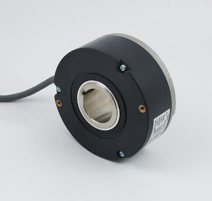
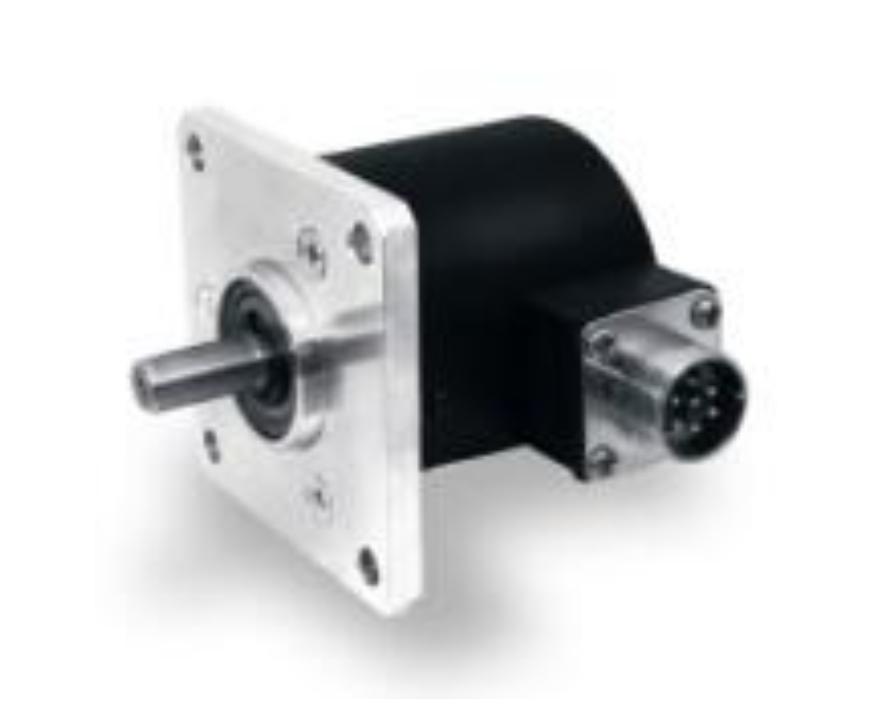
Rotary encoder is a device used to measure the speed and cooperate with PWM technology to achieve fast speed adjustment. Through photoelectric conversion, the photoelectric rotary encoder can convert the angular displacement and angular velocity of the output shaft into corresponding electrical pulses in digital quantities. Output. Rotary encoder is divided into single output and dual output. Technical parameters mainly include the number of pulses per revolution (10-9000P/R are available), and power supply voltage. Single output means that the output of the rotary encoder is a set of pulses, while the dual output rotary encoder outputs two sets of A/B phase difference pulses of 90 degrees. These two sets of pulses can not only measure the speed, but also determine the rotation. Direction. Shaft type: Shaft type can be divided into clamping flange type, synchronous flange type and servo mounting type. Shaft sleeve type: The shaft sleeve type can be divided into half hollow type, full hollow type and large diameter type. According to the working principle of the encoder, it can be divided into: photoelectric type, magnetoelectric type and contact brush type. Encoders can be classified into two types: incremental type and type according to the different engraving methods of the code disc.
Serial transmission corresponds to the usual parallel transmission that outputs multiple bits of data at the same time. It can be used in the form of serialized output data by a transmission line. The purpose is to save the connection. The signal is converted into a parallel signal on the receiving side and used. The hollow shaft type (hollow shaft type) has a hollow shaft shape. By directly connecting the drive side shaft to the hollow hole, space in the shaft direction can be saved. The rotating plate (disk) of the metal disk encoder is made of metal with a leaf spring as a buffer to absorb the vibration of the drive shaft. Compared with the glass rotating plate (disk), it has stronger impact resistance. However, due to the limitation of slit processing, it cannot be applied to high resolution. One of the installation methods of the encoder of the servo device is to use the accessories for the servo device to press the flange of the encoder and fix it. In the temporarily fixed state, the position of the encoder can be adjusted in the rotation direction, so it is suitable for the situation that needs to coincide with the origin of the encoder.
Therefore, it is generally used on machine tools with special needs. Rotary encoder is a rotary sensor that converts the rotation displacement into a series of digital pulse signals. These pulses can be used to control the angular displacement. If the encoder is combined with a gear bar or screw screw, it can also be used for measurement Linear displacement. However, encoders can be divided into two types: contact type and non-contact type according to the reading mode; rotary encoders can be divided into two types: incremental type and two types according to the working principle. Each position of the type encoder corresponds to a certain digital code, so its indication can only be related to the start and end positions of the measurement, and has nothing to do with the intermediate process of the measurement. The incremental encoder converts the displacement into a periodic electric signal, and then converts this electric signal into a counting pulse, and the number of pulses is used to indicate the magnitude of the displacement. Using a rotary encoder can help us know what the motor speed is. As we all know, the speed of the motor needs to be controlled within a certain range.
There are many engraved lines on the encoder optical code disc, and each engraved line is arranged in 2 lines, 4 lines, 8 lines, and 16 lines in sequence. In this way, at each position of the encoder, by reading the pass of each engraved line , Dark, obtain a set of binary codes (Gray codes) from the zero power of 2 to the n-1 power of 2, which is called an n-bit encoder. Such an encoder is determined by the mechanical position of the encoder, and it is not affected by power failure or interference.
Note Do not apply direct impact to the shaft during installation. The connection between the encoder shaft and the machine should use a flexible connector. When installing the connector on the shaft, do not hard press it in. Even if the connector is used, due to improper installation, a load larger than the allowable load may be applied to the shaft, or core shifting may be caused, so be careful. Bearing life is related to service conditions and is greatly affected by bearing load. If the bearing load is smaller than the specified load, the bearing life can be greatly extended. Do not disassemble the rotary encoder. Doing so will damage the oil and drip resistance. Anti-drip products should not be immersed in water or oil for a long time. If there is water or oil on the surface, wipe it dry. Note Do not apply direct impact to the shaft during installation. The connection between the encoder shaft and the machine should use a flexible connector. When installing the connector on the shaft, do not hard press it in. Even if the connector is used, due to improper installation, a load larger than the allowable load may be applied to the shaft, or core shifting may be caused.
Phase A and Phase B are expressed as a phase difference of 90° in electrical angle. CW is the direction of clockwise rotation (ClockWise). Viewed from the side of the shaft, it rotates to the right. In this rotation direction, the incremental type usually outputs phase A before phase B, and the type is the code increase direction. When the CW direction is reversed, it is the ratio of the output efficiency ratio of CCW (CounterClockWise) to the average pulse cycle time output when the shaft rotates at a fixed speed to the H bit time of one cycle. The frequency of the signal obtained in response to the frequency response signal. Rise time, fall time output pulse 10 to 90% of the time. Output circuit (1) The open-collector output uses the transistor emitter of the output circuit as a common type, and the collector is an open output circuit. (2) The voltage output is a common type with the emitter of the transistor of the output circuit, a resistor is inserted between the collector and the power supply, and the output of the collector that changes with the voltage is output.
So as not to damage the output circuit of the BEN encoder. The motor and other equipment connected to the encoder should be well grounded and free of static electricity. Before starting the machine, check carefully whether the product manual matches the BEN encoder model and whether the wiring is correct. Use shielded cables when wiring. For long-distance transmission, signal attenuation factors should be considered, and an output method with low output impedance and strong anti-interference ability should be selected. Avoid using in strong electromagnetic wave environment. In terms of environment, the encoder is a precision instrument. When using it, pay attention to whether there are vibration sources and interference sources around. Please pay attention to whether the ambient temperature and humidity are within the required range of the instrument. Encoders that are not leak-proof structures should not be splashed with water, oil, etc., and a protective cover should be added when necessary. It is relative to the increment. As the name implies, the so-called encoder output signal is in the process of one or more weeks of operation. The output code value corresponding to each position and angle is corresponding, so it has the function of power-down memory. Each position of the encoder is determined by the mechanical position.
When the shaft of the incremental incremental encoder rotates, there is a corresponding phase output. The determination of the direction of rotation and the increase or decrease of the number of pulses need to be realized with the help of the direction circuit and counter at the rear. The counting starting point can be set arbitrarily, and unlimited accumulation and measurement of multiple turns can be realized. It is also possible to use the Z signal for each pulse transmitted as a reference mechanical zero position. When the pulse is fixed and the resolution needs to be improved, two signals with a 90-degree phase difference A and B can be used to double the original pulse number. In the case of the axis rotator of the value encoder, there is a code (binary, BCD code, etc.) output corresponding to the position one-to-one, and the positive and negative direction and the position of the displacement can be determined from the change of the code size, without the need to determine the circuit. It has a zero code. When the power is cut off or turned off and then turned on and re-measured, the code of the power cut or shut down position can still be read accurately, and the zero code can be found accurately. In general, the measuring range of the value encoder is 0 to 360 degrees.
The single-rotation type data has the same features as the normal type. The rotation amount data can also be output as data. According to the detection method of the rotation amount data, the type of battery that supports the power supply when the power is disconnected is selected or not required. The use of incremental encoders can be applied to the occasions where the encoder's position is detected in any rotating state. The structure of the detection unit and the model are basically the same. Using partial single-rotation signals, accumulate the single-rotation amount of one rotation according to the internal counter, and use it as a code to output multi-rotation data. The rotation angle uses the 2n code as the value and is output in parallel. Therefore, if you hold the output amount of output code digits. When the resolution is larger, the output will increase by directly reading the output code to detect the rotation position. Once the encoder is installed in the machine, the zero position of the input rotation axis can be determined. Generally, the zero position is used as the origin of the coordinate, and the rotation angle is digitally output. In addition, data errors will not occur due to interference or the like.
The incremental encoder converts the displacement into a periodic electric signal, and then converts this electric signal into a counting pulse, and the number of pulses represents the magnitude of the displacement. Each position of the type encoder corresponds to a certain digital code, so its indication is only related to the start and end positions of the measurement, and has nothing to do with the middle process of the measurement. Rotary incremental encoder outputs pulses while rotating, and knows its position through counting equipment. When the encoder is not moving or the power is cut off, it relies on the internal memory of the counting equipment to remember the position. In this way, when the power is off, the encoder cannot move. When the power is on, the encoder cannot lose the pulse due to interference during the pulse output. Otherwise, the zero point of the counting device will shift, and this deviation There is no way to know the amount of shift, only after the wrong production results appear. The solution is to increase the reference point. Every time the encoder passes the reference point, the reference position is corrected into the memory position of the counting device.
The signal output has sine wave (current or voltage), square wave (TTL, HTL), open collector (PNP, NPN), push-pull multiple forms, of which TTL is a long-line differential drive (symmetrical A, A-; B, B -;Z,Z-), HTL is also called push-pull and push-pull output. The signal receiving device interface of the encoder should correspond to the encoder.
Signal connection—The pulse signal of the encoder is generally connected to the counter, PLC, and computer. The modules connected to the PLC and the computer are divided into low-speed modules and high-speed modules, and the switching frequency is low or high.
But special models can also achieve multi-turn measurement. Sine wave sine wave encoder is also an incremental encoder, the main difference is that the output signal is a sine wave analog signal, not a digital signal. Its appearance is mainly to meet the needs of the electrical field-as a feedback detection element for motors. On the basis of comparing with other systems, people can use this kind of encoder when people need to improve the dynamic characteristics. In order to ensure good motor control performance, the feedback signal of the encoder must be able to provide a large number of pulses, especially when the speed is very low, the use of traditional incremental encoders to generate a large number of pulses, there are problems in many aspects When the motor rotates at a high speed (6000rpm), it is difficult to transmit and process digital signals. In this case, the bandwidth required to process the signal to the servo motor (such as 10,000 pulses per revolution of the encoder) will easily exceed the MHz threshold; on the other hand, the use of analog signals greatly reduces the above-mentioned hemp.
E69-C06B type coupler, tightening torque 2.5kgf·cm; E69B-Cl0B type coupler, tightening torque 4.5kfg·cm. Step 4: Connect the power output line. The power supply must be turned off when wiring. Step 5: Check that the power supply is put into use. Precautions for the installation of the rotary encoder 1. When using a standard coupler, 2. When the connecting belt and gear are combined, first support it with other bearings, and then combine the rotary encoder and the coupler. 3. When connecting gears, be careful not to subject the shaft to excessive load. 4. When tightening the rotary encoder with screws, apply a tightening torque of about 5kfg·cm. 5. When fixing the main body for wiring, do not pull the wire with a force greater than 3kg. 6. When using reversible rotation, pay attention to the installation direction of the body and the direction of addition and subtraction. 7. To set the device origin and the Z of the encoder relative to time, the coupler must be installed while determining the Z phase output. 8. Do not allow water droplets and oil to stick to the body during use.
Press the reference position first to reset the count value of the counting position, and then use the counter to accumulate the number of pulses sent from this position. Therefore, the reference position can be arbitrarily selected, and the amount of rotation can be detected infinitely. Its specialty is that a circuit can be added to generate 2 times and 4 times the number of pulses of a cycle signal, which improves the current resolution (Note). In addition, the Z-phase signal generated per revolution can be used as the origin within 1 revolution. Note. When high resolution is required, a 4-times multiplying circuit can generally be used. (If the rising and falling waveforms of Phase A and Phase B are differentiated respectively, 4 times the output can be obtained, and the resolution is 4 times). When the optical pattern is written on the disk while rotating with the shaft, the light passing through the two slits will be transmitted and blocked accordingly. This light is converted into electric current by the light-receiving elements facing the respective slits, and after waveform shaping, it becomes two rectangular wave outputs. The other two slits should be arranged at 1/4 pitch of the phase difference with the rectangular wave output.
If immersed inside, it will cause malfunction. A rotary encoder is a sensor that converts the mechanical displacement of rotation into an electrical signal, processes the signal, and detects position, speed, etc. The sensor that detects linear mechanical displacement is called a linear encoder. Features (1) According to the rotation displacement of the shaft, the output is combined with the shaft through a coupling, and the rotation displacement can be directly detected. ;②There is no need to return to origin when starting. In the case of the (model only) model, the rotation angle is output in parallel as a numerical value. ③The rotation direction can be detected. In the incremental type, the output time of the A phase and B phase can be used, and in the type, the rotation direction can be grasped by the increase or decrease of the code. ④Please select the appropriate sensor according to the rich resolution and output model. According to the required accuracy, cost, connection circuit, etc., select a suitable sensor. The model can output pulse trains according to the rotational displacement of the shaft. The method is to count the number of output pulses by other counters, and detect the amount of rotation by counting. Want to know the rotation of a certain input shaft position.
To accurately measure the zero pulse, regardless of the direction of rotation, the zero pulse is output as the high-order combination of the two channels. Due to the phase difference between the channels, the zero pulse is only half the pulse length. Some encoders with early warning signal also have an alarm signal output, which can give an alarm for power failure and light-emitting diode failure, so that the user can replace the encoder in time. The basic output mode has poor anti-interference ability and short output effective distance. It is used for incremental encoder output in rotary encoders, and it is seldom used now. It combines PNP and NPN output, symmetrical positive and negative signal output, can be easily connected to single-ended reception, strong anti-interference ability (differential reception); transmission distance 100m. Transmission medium: twisted pair (differential reception); all wires, optical fiber, radio (single-ended reception). High-frequency characteristics: Well, other interface methods include RS232 (C), RS485 and SSI commonly used by encoders. The total number of pulses output by various field routes/the number of pulses output by the rotary encoder one revolution.
The C and D signals are reversed and superimposed on the A and B phases to enhance the stable signal; in addition, a Z-phase pulse is output every revolution to represent the zero reference position. Since the phases A and B differ by 90 degrees, the encoder's forward and reverse rotation can be judged by comparing the phase A or the B phase. The zero reference position of the encoder can be obtained through the zero pulse. The materials of the encoder code disc are glass, metal, plastic. The glass code disc is deposited on the glass with very thin scribe lines, which has good thermal stability and high precision. The metal code disc is directly engraved with through and impassable lines and is not fragile. However, due to the certain thickness of metal, the accuracy is limited, and its thermal stability is one order of magnitude worse than that of glass. Plastic code discs are economical, and their cost is low, but accuracy, thermal stability, and life are worse. . Signal output The signal output has sine wave (current or voltage), square wave (TTL, HTL), open collector (PNP, NPN), push-pull multiple forms, of which TTL is a long-line differential drive (symmetrical A, A-; B ,B-;Z,Z-), HTL is also called push-pull and push-pull transmission.
FEATURED PRODUCTS


Custom HTML Block
This is a custom sub-title.
Lorem ipsum dolor sit amet, con sec tetur elitad adipiscing Cras non placerat mi.