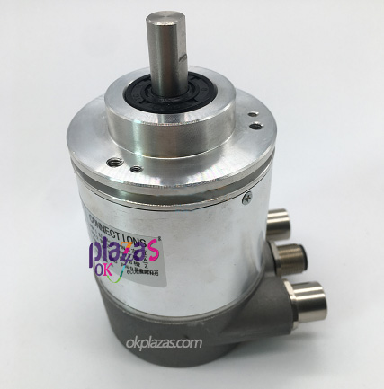
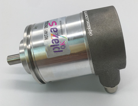
Absolute encoder okplazas58L10-MA4096
Absolute encoder okplazas58L10-MA4096
Absolute Encoder / Absolute Encoder
Absolute encoders are divided into single-turn absolute and multi-turn absolute. The code channel is designed using the principles of Gray code, matrix code, vernier code, pseudo-random code, etc. When the shaft rotates, there is a code output corresponding to the position. From the change of the code size, the positive and negative direction and the position of the displacement can be judged, without the need to judge the circuit. It has an absolute zero code. When the power is cut off or shut down, the code of the power cut or shut down position can still be read out and the zero code can be accurately found when the machine is turned on and re-measured.
The company's profibus absolute rotary encoder strictly complies with the requirements of the conventional catalog of electronic products and the relevant content of the electromagnetic compatibility standard 89/336/CEE.
The user can change the output value of the encoder in the following ways:
Parameter
Paraphrase
Direction of rotation
The encoder increases the count when rotating clockwise or counterclockwise.
Resolution per revolution
(Resolution per revolution)
The number of steps corresponding to each revolution of the encoder.
Total resolution
This parameter represents the maximum value that can be set for the output position.
Preset value
The preset value is the value set by the user to any position of the encoder shaft. The preset value must not exceed "total resolution".
Profibus field bus overview
There are three types of Profibus fieldbus in the market: Profibus-FMS, Profibus-PA and Profibus-DP. The company's Profibus absolute encoder is designed in accordance with the Profibus-DP standard.
The maximum data transmission rate of the Profibus-DP interface of the absolute encoder is 12M baud. The data is output in binary code.
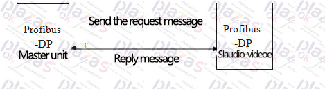

Profibus-DP has the following two different data transmission modes:
DDLM_Set_Prm MODE: configuration and parameterization phase, which occurs actively when the system starts to work.
DDLM_Data_Exchange MODE: "Normal operation mode", the master device sends an inquiry request, and the rotary encoder responds to the actual position information.
Installation Notes
Connect Profibus encoders by connecting various interfaces on the cover. The encoder is connected through a 15-pin D-shaped female socket. The power cord and the bus are connected to the screw terminals of the connection board through cables.
Magnetoelectric encoder product information
Node address
The node address can be set by the cross switch under the wiring cover. The ratio (×10 or ×1) is marked below the switch. The allowed setting of the address is from 3 to 99, and each address can only be unique in the entire system. The rotary encoder reads the device address after power on. The user can move the wiring cover through the two screws on the back cover during installation.
-
The principle and application field of Autonics panel products (handling)
 June 12, 2021
 -
New product launch SRH1 series single-phase SSR with integrated heat sink
 June 12, 2021
 -
New product launch SRH1 series single-phase SSR with integrated heat sink
 June 12, 2021
 -
Otto protection grade IP69K new product launched Ø18mm cylindrical (SUS316L housing) photoelectric sensor BRQT series
 June 12, 2021
 -
Autonics adds shading motion mode sensor
 June 12, 2021