Design of Drive Motor for Quadrature Encoder Based on STM32
Design of Drive Motor for Quadrature Encoder Based on STM32
1. Encoder principle
What is orthogonal? If the two signals are 90 degrees out of phase, the two signals are called quadrature. Since the two signals differ by 90 degrees, the direction can be determined according to which of the two signals comes first.
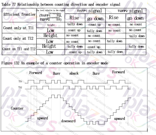
The TI12 mode is used here. For example, when T1 is at the rising edge and T2 is at low level; when T1 is at the falling edge and T2 is at high level, count up. The advantage is that when there is a glitch, it will automatically filter out +1 -1 glitch.
2. Encoder interrupt
Since the encoder is based on the timer, the interrupt of the encoder is actually the interrupt of the timer. That is to say, the timer adds a number (or subtracts a number) at regular intervals, and generates an interrupt when the number reaches the preset value, while the encoder adds a number (or subtracts a number) for every valid pulse. When the number reaches the preset value, an interrupt is generated. If the preset value is 1000, the difference between the encoder and the timer interrupt is that an interrupt is generated when the value reaches 999 when the encoder reverses, and an interrupt is also generated when the encoder reaches 0 in the forward direction. The two interrupts are indistinguishable in hardware, which causes a misjudgment in a situation.
3. Cases not considered by the STM32 encoder
Imagine, if the default value of the encoder is 1000, what should we do if we interrupt the encoder's forward rotation and immediately reverse it? According to the above statement, two identical interrupts will be generated at this time. If it is not processed in the algorithm, it is most likely to be considered to have walked forward twice. But in fact it did not. Therefore, at this time, you must determine the walking situation in combination with the direction (the DIR register bit is used to determine the direction) or read the count register bit once after the interrupt is generated (see whether it is 999 or 0 to determine the current direction). Only if the last time is positive and this time is also positive, the distance is added.
4. STM32f1 series timer 16-bit problem
I use STM32 timer 3 to work in encoder mode, and the encoder position can be obtained normally, but because there are only 16 bits for counting, and the number of bits is not enough, I want to expand to 32 bits. You can use the timer internal connection to connect the timer The overflow of 3 is sent to timer 2, and timer 2 is used as the high bit. It is normal during forward rotation, but an error occurs during reverse rotation. Another way of thinking is to make an interrupt that is generated every 10ms, and call the following code in the interrupt. In the following code, MAX_COUNT is a value larger than the maximum count that may occur within 10ms, and ENCODER_TIM_PERIOD is the period value of the timer , It is better to be larger than MAX_COUNT, then define a 32-bit signed variable, such as currentCount, and then execute currentCount += Enc_GetCount() every 10ms; you only need to read the value of currentCount to get the displacement information.
s16 Enc_GetCount(void)
{
static u16 lastCount = 0;
u16 curCount = ENCODER_TIM-》CNT;
s32 dAngle = curCount-lastCount;
if(dAngle 》= MAX_COUNT) {
dAngle -= ENCODER_TIM_PERIOD;
}else if(dAngle《 -MAX_COUNT){
dAngle += ENCODER_TIM_PERIOD;
}
lastCount = curCount;
return (s16) dAngle;
}
5. Some other information
1. The encoder has an upper limit of speed. If the upper limit is exceeded, it will not work properly. This is a hardware limitation. In principle, the more the number of lines, the lower the speed. This should be noted when selecting the type. The output of the encoder is generally on. It is leaked, so the io of the microcontroller must be pulled up to the input state.
2. After the timer is initialized, the value of the CNT register at any time is the position information of the encoder. It will increase and decrease when it rotates forward. This part does not require software intervention. The value of TIM_Period given during initialization should be code rounding. The scale value of the circle will automatically be corrected to this number after subtraction and overflow. Add more than this value and return to 0.
3. If you want to expand to multi-turn counting and need overflow interruption, just add and subtract direction bits for upper-turn counting in the program.
4. The input pin of each timer can be filtered by software
5. In the application, if there is no absolute position signal or the count before the absolute position signal is not received after the initialization is completed, only the relative count can be used. After receiving the absolute position signal, modify the value of CNT again. The encoder generally has a zero position signal, which can be combined with the timer capture input. After power on, you need to move back and forth to find this position.
6. Even if there is a filter count value, there will be occasional errors. It is normal to count one more or one less count per revolution, especially when the speed is relatively high. It is very obvious to have an absolute position signal to make corrections. Necessary. The absolute position signal does not need to be at the zero position point, and the CNT can be corrected to a fixed value after receiving this signal.
7. Turning on the input interrupt of the timer can achieve the effect of processing each step count, but you may not be able to handle it during high-speed operation.
-
The principle and application field of Autonics panel products (handling)
 June 12, 2021
 -
New product launch SRH1 series single-phase SSR with integrated heat sink
 June 12, 2021
 -
New product launch SRH1 series single-phase SSR with integrated heat sink
 June 12, 2021
 -
Otto protection grade IP69K new product launched Ø18mm cylindrical (SUS316L housing) photoelectric sensor BRQT series
 June 12, 2021
 -
Autonics adds shading motion mode sensor
 June 12, 2021