Encoder, what does encoder mean
Encoder, what does encoder mean
Encoder, what does encoder mean
Encoder
An encoder is a device that compiles and converts a signal (such as a bit stream) or data into a signal form that can be used for communication, transmission, and storage.
The encoder converts angular displacement or linear displacement into electrical signals. The former becomes a code disc and the latter is called a yardstick. Encoders can be divided into contact type and non-contact type according to the read mode. The contact type uses a brush to output. A brush touches the conductive area or the insulating area to indicate whether the status of the code is "1" or "0"; the non-contact type receiving sensitive element is a photosensitive element or a magnetic sensitive element. The light-transmitting area and the opaque area indicate whether the state of the code is "1" or "0". The collected physical signal is converted into an electrical signal readable by the machine code through the binary code of "1" and "0" Used for communication, transmission and storage.
According to the working principle, encoders can be divided into two types: incremental and absolute. The incremental encoder converts the displacement into a periodic electric signal, and then converts this electric signal into a counting pulse, and the number of pulses is used to indicate the magnitude of the displacement. Each position of the absolute encoder corresponds to a certain digital code, so its indication is only related to the start and end positions of the measurement, and has nothing to do with the middle process of the measurement. (REP)
From proximity switch, photoelectric switch to rotary encoder
Positioning in industrial control, the applications of proximity switches and photoelectric switches have been quite mature and very useful. However, with the continuous development of industrial control, there are new requirements. In this way, the application advantages of using a rotary encoder are highlighted:
Informatization: In addition to positioning, the control room can also know its specific location;
Flexibility: Positioning can be flexibly adjusted in the control room;
On-site installation is convenient, safe, and long-lived: a fist-sized rotary encoder can measure distances from a few μ to several hundreds of meters, with n stations. As long as the safety installation problem of a rotary encoder is solved, it can be avoided Many proximity switches and photoelectric switches are troublesome to mechanically install on site, and are easily damaged by high temperature and moisture. Because it is a photoelectric code wheel, there is no mechanical loss, as long as the installation position is accurate, its service life is often very long.
Multifunctionalization: In addition to positioning, it can also remotely transmit the current position and convert the movement speed, which is especially important for applications such as inverters and stepping motors.
Economy: For multiple control stations, only the cost of a rotary encoder is required, and the more important installation, maintenance, and loss costs are reduced, and the service life is increased, and its economy is gradually highlighted.
As mentioned above, rotary encoders have been more and more widely used in various industrial control applications.
From incremental encoder to absolute encoder
Rotary incremental encoder outputs pulses when it rotates, and knows its position through the counting device. When the encoder does not move or power is off, the internal memory of the counting device is used to remember the position. In this way, when the power is off, the encoder cannot move. When the power is on, the encoder cannot lose the pulse due to interference during the pulse output. Otherwise, the zero point of the counting device will shift, and this deviation There is no way to know the amount of displacement, only after the wrong production results appear.
The solution is to increase the reference point. Every time the encoder passes the reference point, the reference position is corrected into the memory position of the counting device. Before the reference point, the accuracy of the position cannot be guaranteed. For this reason, in industrial control, there are methods such as first finding the reference point for each operation, turning on the machine, and so on.
For example, the positioning of a printer scanner is based on the principle of an incremental encoder. Every time we turn it on, we can hear a crackling sound. It is looking for the reference zero point before it works.
This method is more troublesome for some industrial control projects, and it is not even allowed to switch on the machine (the exact position must be known after the machine is turned on), so the absolute encoder appears.
Absolute rotary photoelectric encoder, because of its absolute unique position, anti-interference, no power-down memory, has been more and more widely used in angle, length measurement and positioning control in various industrial systems.
There are many engraved lines on the optical code disc of absolute encoder, and each engraved line is 2 lines, 4 lines, 8 lines and 16 lines in turn. . . . . . Arrangement, in this way, at each position of the encoder, by reading the open and dark of each engraved line, a set of unique binary codes from the zero power of 2 to the n-1 power of 2 (Gray Code), which is called an n-bit absolute encoder. Such an encoder is determined by the mechanical position of the encoder, and it is not affected by power outages and interference.
The uniqueness of each position determined by the mechanical position of the absolute encoder. It does not need to be memorized, does not need to find a reference point, and does not need to be counted all the time. When it needs to know the position, when to read its position. In this way, the anti-interference characteristics of the encoder and the reliability of the data are greatly improved.
Since absolute encoders are significantly better than incremental encoders in positioning, they have been increasingly used in industrial control positioning. Absolute encoders have a large number of output digits due to their high precision. If parallel output is still used, each output signal must be well connected. For more complex working conditions, it must be isolated and the number of connecting cables is large. Bringing a lot of inconvenience and reducing reliability. Therefore, the absolute encoder in the multi-digit output type generally uses serial output or bus type output. The most commonly used serial output of the absolute encoder produced in Germany is SSI (synchronous Line output).
From single-turn absolute encoder to multi-turn absolute encoder, the single-turn absolute encoder is rotated to measure each engraved line of the optical code disc during rotation to obtain a unique code. When the rotation exceeds 360 degrees, the code returns To the origin, this does not comply with the principle of absolute coding uniqueness. Such an encoder can only be used for measurement within a rotation range of 360 degrees, which is called a single-turn absolute encoder.
If you want to measure the rotation range beyond 360 degrees, you must use a multi-turn absolute encoder.
The encoder manufacturer uses the principle of clock gear mechanism. When the center code wheel rotates, another set of code discs (or multiple sets of gears, multiple sets of code discs) are driven by gears, and the number of turns is added to the single-turn encoding. Encoding, in order to expand the measuring range of the encoder, such an absolute encoder is called a multi-turn absolute encoder, it is also determined by the mechanical position code, each position code is unique and does not repeat, without the need to remember.
Another advantage of multi-turn encoders is that due to the large measuring range, the actual use is often richer, so there is no need to laboriously find the change point during installation, and a certain intermediate position can be used as the starting point, which greatly simplifies the difficulty of installation and debugging.
Multi-turn absolute encoder has obvious advantages in length positioning, and it has been increasingly used in industrial control positioning.
The mechanical installation and use of absolute rotary encoder:
The mechanical installation of absolute rotary encoder has various forms such as high-speed end installation, low-speed end installation, and auxiliary mechanical device installation.
High-speed end installation: Installed on the shaft end of the power motor (or gear connection). This method has the advantage of high resolution. Since the multi-turn encoder has 4096 turns, the number of motor rotations is within this range, which can be fully used to increase the range. Resolution, the disadvantage is that after the moving object passes through the reduction gear, there is a gear gap error in the back and forth. It is generally used for one-way high-precision control and positioning, such as roll gap control in steel rolling. In addition, the encoder is directly installed on the high-speed end, and the motor jitter must be small, otherwise the encoder is easily damaged.
Installation at the low speed end: installed after the reduction gear, such as the shaft end of the winding wire rope drum or the shaft end of the last reduction gear, this method has no gear back and forth clearance, the measurement is more direct, and the accuracy is higher. This method generally measures the length Distance positioning, such as various lifting equipment, feeding trolley positioning, etc.
Auxiliary mechanical installation:
Commonly used gears and racks, chain belts, friction wheels, rope winding machinery, etc.
Optical encoder features
‧ Using photoelectric sensor technology
‧ Surface mount leadless package
‧ Provide two-channel digital signal output
‧ Counting frequency: 0~100 KHz
‧ Power supply voltage DC5.0V, 5~12V, 12~24V
‧ Working temperature: -10 to 70oC
‧ Encoding resolution: 180 LPI
‧ Comply with RoHS environmental standards
Encoder working principle
Absolute pulse encoder: APC
Incremental pulse encoder: SPC
Both are generally used in the detection elements of speed control or position control systems.
Rotary encoder is a device used to measure speed. It is divided into two types: single output and dual output. Technical parameters mainly include the number of pulses per revolution (dozens to thousands of them), and power supply voltage. Single output means that the output of the rotary encoder is a set of pulses, while the dual output rotary encoder outputs two sets of pulses with a phase difference of 90 degrees. The two sets of pulses can not only measure the speed, but also determine the direction of rotation.
The difference between incremental encoder and absolute encoder
If the encoder is divided into signal principle, there are incremental encoder and absolute encoder.
Incremental encoder (rotary type)
working principle:
A photoelectric code disc with an axis in the center, on which there are circular and dark engraved lines, is read by photoelectric transmitter and receiver, and obtains four groups of sine wave signals combined into A, B, C, D, each sine wave A phase difference of 90 degrees (360 degrees relative to a cycle), the C and D signals are reversed and superimposed on the A and B phases to enhance the stable signal; in addition, a Z-phase pulse is output every revolution to represent the zero reference Bit.
Since the phase A and B are 90 degrees apart, the encoder's forward and reverse rotation can be judged by comparing the phase A or the B phase. The zero reference position of the encoder can be obtained through the zero pulse.
The materials of the encoder code disc are glass, metal, plastic. The glass code disc is deposited on the glass with very thin score lines, which has good thermal stability and high precision. The metal code disc is directly engraved with through and impassable lines and is not fragile. However, due to the certain thickness of metal, the accuracy is limited, and its thermal stability is one order of magnitude worse than that of glass. Plastic code discs are economical, and their cost is low, but accuracy, thermal stability, and life are worse. .
Resolution—The number of open or dark engraved lines provided by the encoder per 360 degree rotation is called resolution, which is also called resolution division, or directly called the number of lines, generally 5 to 10,000 lines per revolution.
Signal output:
The signal output has sine wave (current or voltage), square wave (TTL, HTL), open collector (PNP, NPN), push-pull multiple forms, of which TTL is a long-line differential drive (symmetrical A, A-; B, B -;Z,Z-), HTL is also called push-pull and push-pull output. The signal receiving device interface of the encoder should correspond to the encoder.
Signal connection—The pulse signal of the encoder is generally connected to the counter, PLC, and computer. The modules connected between the PLC and the computer are divided into low-speed modules and high-speed modules, and the switching frequency is low or high.
Such as single-phase connection, used for single direction counting and single direction speed measurement.
A.B two-phase connection, used for forward and reverse counting, judgment of forward and reverse and speed measurement.
A, B, Z three-phase connection, used for position measurement with reference position correction.
A, A-, B, B, B-, Z, Z-connections, due to the connection with symmetrical negative signals, the electromagnetic field contributed by the current to the cable is 0, the attenuation is the smallest, the anti-interference is the best, and it can be transmitted over a long distance.
For TTL encoders with symmetrical negative signal output, the signal transmission distance can reach 150 meters.
For HTL encoders with symmetrical negative signal output, the signal transmission distance can reach 300 meters.
Definition and function of encoder:
In digital systems, it is often necessary to transform a certain information (input) into a certain code (output). Arrange binary codes according to certain rules, such as 8421 codes, Gray codes, etc., so that each group of codes has a specific meaning (representing a certain number or control signal) is called a code. The logic circuit with encoding function is called encoder. The encoder has several inputs, and only one input signal is converted into a binary code at a certain time. If an encoder has N input terminals and n output terminals, the relationship between the output terminal and the input terminal should satisfy the relationship N≤2n. For example, 8-wire-3 wire encoder and 10-wire-4 wire encoder have 8 input, 3-bit binary code output and 10-input, 4-bit binary code output respectively.
1.4 line-2 line encoder
The working principle of the encoder with 4 inputs and 2 binary outputs is analyzed below. The function of 4-wire-2 wire encoder is shown in Table 5.2.1.
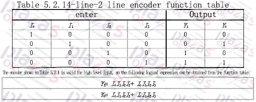
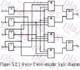
Draw the logic diagram according to the logic expression as shown in Figure 5.2.1. The logic circuit can realize the functions shown in Table 5.2.1, that is, when one of the inputs of I0~I3 is 1, the output Y1Y0 is the corresponding code. For example, when I1 is 1, Y1Y0 is 01. There is one more issue here for readers' attention. When I0 is 1, I1~I3 are all 0 and I0~I3 are all 0, Y1Y0 are all 00, and these two situations must be distinguished in practice. This problem is left to be solved later. Of course, the encoder can also be designed to be active low.
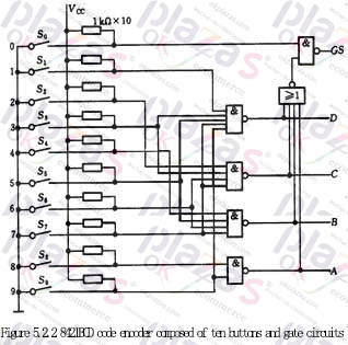
2. Keyboard input 8421BCD code encoder:
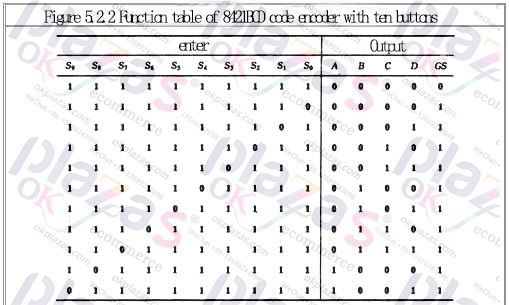
The keyboard input logic circuit of the computer is composed of an encoder. Figure 5.2.2 is an 8421 code encoder composed of ten buttons and gate circuits. Its functions are shown in Table 5.2.2, where S0~S9 represent ten buttons, that is, input keys corresponding to decimal numbers 0-9. They The corresponding output codes are just 8421BCD codes, and they are also used as logic variables. ABCD is the output code (A is the highest bit), and GS is the control enable flag.
Analyzing the function table and logic circuit, we can know that: ①The encoder is input low-level valid; ②When any one of the keys S0~S9 is pressed, that is, when one of the input signals is valid, GS =1, it means there is signal input, and only when S0~S9 are all high level, GS=0, it means no signal input, the output code 0000 at this time is invalid code. This solves the problem of how to distinguish the two cases where the output is all 0.
In summary, the encoder can be summarized as follows:
1. The number of input terminals of the encoder N (the number of information to be encoded) and the number of output terminals n (the number of bits of the resulting code) should satisfy the relationship N≤2n.
2. Each input terminal of the encoder represents a binary number, decimal number or other information symbol, and only one input signal is allowed at a time among the N input terminals (input low level is valid or input high level Valid), the output is the corresponding binary code or two-decimal code (BCD code).
3. Correct use of the control end of the encoder can be used to extend the function of the encoder.
-
The principle and application field of Autonics panel products (handling)
 June 12, 2021
 -
New product launch SRH1 series single-phase SSR with integrated heat sink
 June 12, 2021
 -
New product launch SRH1 series single-phase SSR with integrated heat sink
 June 12, 2021
 -
Otto protection grade IP69K new product launched Ø18mm cylindrical (SUS316L housing) photoelectric sensor BRQT series
 June 12, 2021
 -
Autonics adds shading motion mode sensor
 June 12, 2021