Graphic versionThe correct disassembly steps of the encoder
Graphic versionThe correct disassembly steps of the encoder
background:
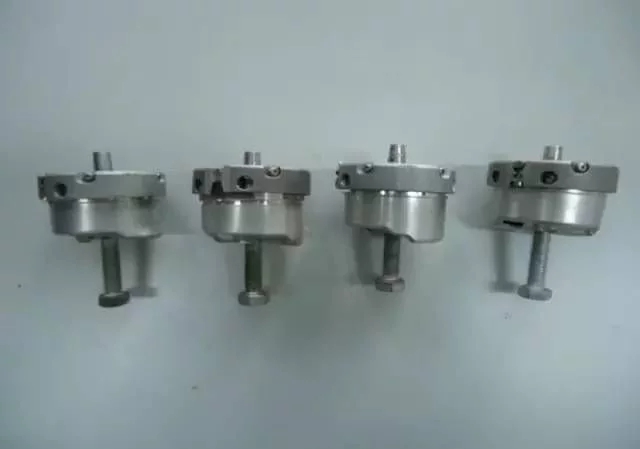
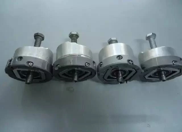
This year IRR has successively received multiple encoders with M10×90MM bolt tails returned from construction sites, as shown in the figure
the reason:
The replacement method was wrong. The encoder was directly screwed out with the 10MM screw on site, causing the 10MM screw to be permanently fastened to the encoder and unable to be removed, resulting in the encoder being scrapped.
Measures:
Compile the correct encoder replacement steps and spread it to the front line of engineering.
tool:
10 × 90mm bolts, 2.5mm inner hexagon, 5mm inner hexagon, 16mm spanner. As shown

step:
1. Check and repair the elevator to make sure there is no one in the car;
2. When the power is off, the indicator light of the inverter is off;
3. Remove the encoder cable;
4.Remove the cover; as shown in the figure
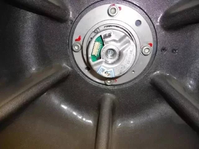
5.Use a 2.5 Allen wrench to loosen the tightening screw of the encoder, and confirm that the encoder can be turned by hand, as shown in the figure
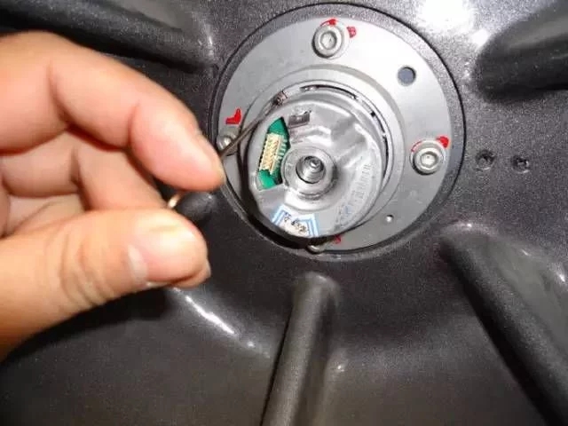
6.Loosen the central hexagon socket screw M5 × 50 with fixed coding about 1.5 turns counterclockwise. This step is very important, as shown in the figure
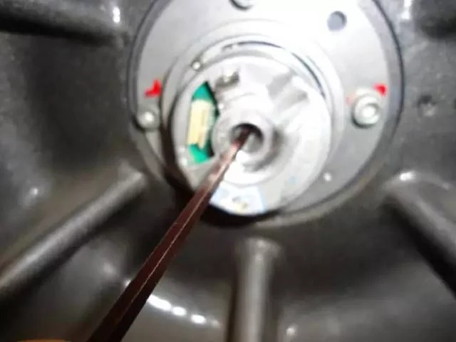
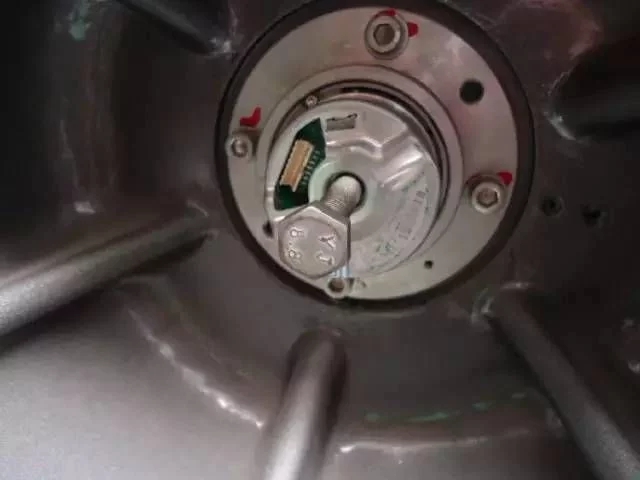
7.Screw the M10 × 90mm bolt in the center of the encoder by hand, as shown in the figure
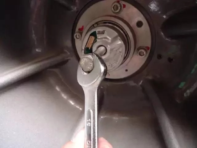
8.Use a 16mm wrench to turn the M10 × 90mm bolt clockwise and press the end face of the M 5 × 50mm hexagon socket screw. When you hear a slight "boom", you feel that the M10 × 90 bolt is loose and the encoder cone is separated from the cone sleeve of the host. Stop the wrench and pull out the 10×90 bolt, as shown in the figure
9.Then exit the inner hexagon M5 × 50mm bolt that fixes the encoder, as shown in the figure
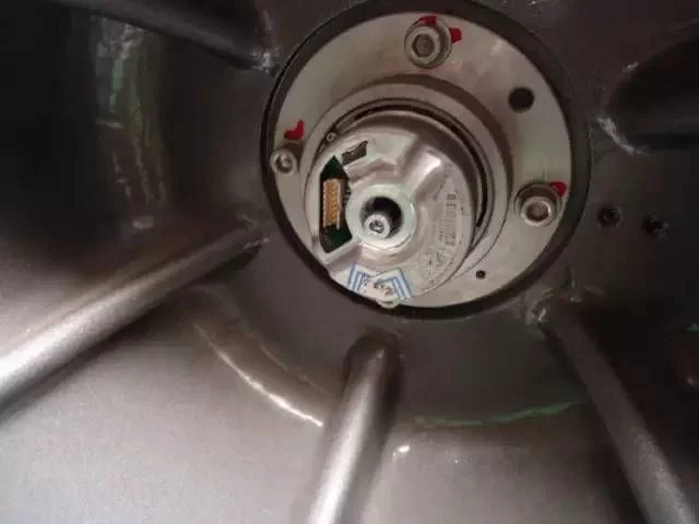
10.Remove the encoder. As shown

-
The principle and application field of Autonics panel products (handling)
 June 12, 2021
 -
New product launch SRH1 series single-phase SSR with integrated heat sink
 June 12, 2021
 -
New product launch SRH1 series single-phase SSR with integrated heat sink
 June 12, 2021
 -
Otto protection grade IP69K new product launched Ø18mm cylindrical (SUS316L housing) photoelectric sensor BRQT series
 June 12, 2021
 -
Autonics adds shading motion mode sensor
 June 12, 2021